Advertisment: Broadband via satellite
Advertisment: Worldwide satellite services from Ground Control Company

www.satsig.net

Satellite Internet Forum.

Welcome, Guest.        Forum rules.
      Home            Login            Register          
Pages: 1

HX 50 install and pointing problem

(Read 42611 times)
Ex Member
Ex Member


Oct 30th, 2007 at 9:37am  
Hi,

I've lurked and researched around here for a while before we made the jump and purchased a system. Now that we have a new HX50 1.2m system from Bentley Walker, we are now having issues getting the dish properly pointed. I searched the forums but couldn't find anything that resolved my problem.

Anyway, I have the right pointing specs for my location at LSA Ananconda (Balad-Iraq).

Elevation=34.1
Azimuth=229.8
Polarisation=42

BW said the RX Polarisation is HORIZONTAL.

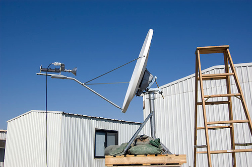
The azimith is dead on and the LNB is rotation to 42 or in the 2 o'clock position. The elevation was eyeballed, but is currently locked down were our Horizon Sat Meter got the best signal at 72. The meter never locked onto or FOUND the W3A Euro satellite, no matter how we adjusted the elevation.

The platform is solid, but in the pics most of the sand bags and the ratchet straps have been removed. The nearest housing unit is cleared by the dish.

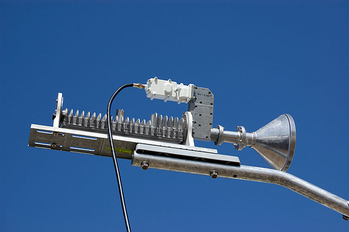
While I was on a long mission, the rest of my crew decided to adjust the feed horn assembly. I put things back to the best of the knowledge, but I wonder if I now have a problem here as well. I am at a loss. 3 days of constant stress and confusion.

Any help is MUCH appreciated.

best,

SGT Carlos Herrera

...
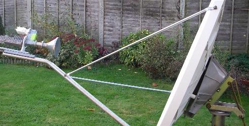
Above: Wrong. LNB is slightly anticlockwise. Polarisation angle not applied to dish.

...
Above: Wrong. LNB is slightly anticlockwise. Polarisation angle not applied to dish.

...
Above: Wrong. LNB is slightly anticlockwise. Polarisation angle not applied to dish.

...
Above: Wrong. LNB is badly anticlockwise - should be exactly in the middle at the top for horizontal polarisation starting position. Polarisation angle not applied to dish.

...
Above: Wrong. LNB is badly anticlockwise - should be exactly in the middle at the top for horizontal polarisation starting position.

...
Above: Wrong. LNB is badly anticlockwise - should be exactly in the middle at the top for horizontal polarisation starting position.

...
Above: Wrong. LNB is badly anticlockwise - should be exactly in the middle at the top for horizontal polarisation starting position.
Back to top
« Last Edit: Feb 7th, 2019 at 4:11pm by Admin1 »  
 
IP Logged
 
Eric Johnston
Senior Member
★★★
Offline


Posts: 2109
Reply #1 - Oct 30th, 2007 at 12:29pm  
Two points:

1. Don't connect up the transmit cable till you have good receive signal, as your modem may commission itself immediately and you don't want this to happen till your pointing is correct. Interrupting it during its 10 minute initialisation and file updating etc may mess it up.

2. The low voltage multi-way cable between the power supply module and the modem should stay plugged in all of the time. Power the modem on and off using the wall mounted AC mains power plug or switch. Pulling out the DC cable with the power on may damage the modem.

Once you have a perfect receive signal (I have 95 here), turn the modem off at the AC mains, connect up the transmit coax cable, power on at the AC mains and leave alone. Speak to the hub. It will completely commission itself in under 10 minutes.

Now, regarding the polarisation and pointing, the present polarisation arrangements are wrong.

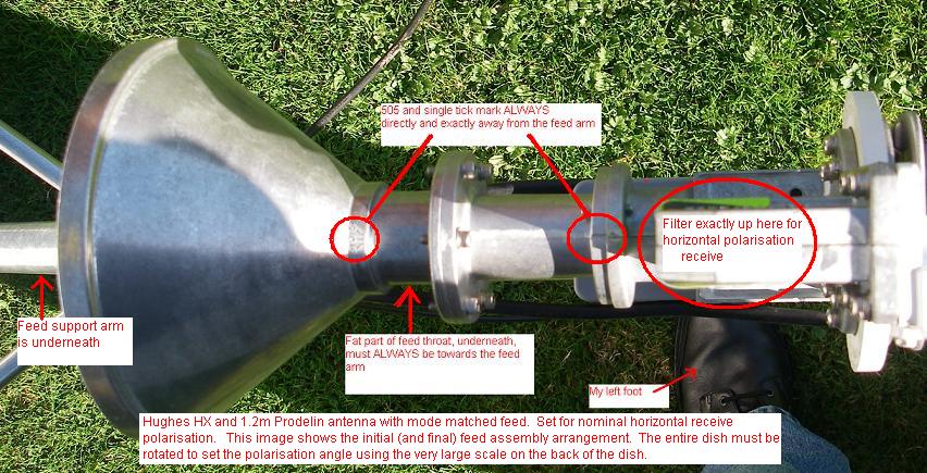
This is a very advanced design antenna with a mode matched feed. The conical feed horn and the short tapered waveguide spacer must always be oriented so that the 505 is away from the feed arm and the single tick mark on the rear spacer flange also must be away from the feed arm. The fat side of the feed throat (which corresponds to 3 mode matching slots on the inside of the throat) must be towards the feed arm.

For nominal horizontal receive polarisation the filter and RF assembly must be attached to the waveguide spacer such that the filter and LNB assembly is uppermost, exactly away from the feed arm. The white rotary scales must be set zero.

...

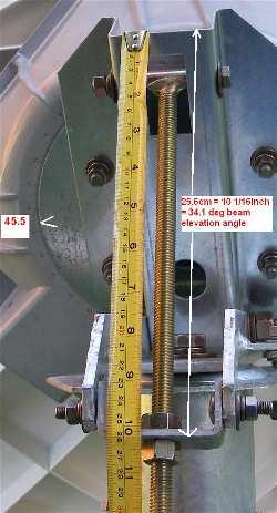
The polarisation adjustment angle is now set by rotating the entire antenna using the big scale on the back of the dish. Loosen the 4 bolts and turn to +45.5 deg. Then tighten (in moderation) the four polarisation bolts. Have confidence in what you are doing, you will be exactly correct.  Use 45.5 deg instead of 42 deg, as Eutelsat 7 east is tilted +3.5 deg clockwise (I think)

Best regards, Eric.
Back to top
« Last Edit: Feb 7th, 2019 at 4:05pm by Admin1 »  
 
IP Logged
 
USN - Retired
YaBB Moderator
★★★★★
Offline


Posts: 837
Kentucky (USA)
Reply #2 - Oct 30th, 2007 at 12:55pm  
Well, I'm only accustomed of late to viewing how things are done on this side of the world. But I see you've not attached the TX cable. Is there a reason for that? I ask, because HughesNet systems aren't suppose to radiate until the modem detects a usable signal as defined by the parameters that you've set into the modem. Even then, it shouldn't radiate until you move into the transmitter isolation adjustments. Your modem DOES have a user interface, doesn't it?

That aside, your search technique differs from that I see most effectively used. I recommend you set the known EL first, then sweep the dish slowly east and west past the calculated magnetic AZ. When the correct signal is detected, alternately fine tune both AZ and EL, until all you get in any direction (up/down, east/west) are dips on the signal strength meter. Then fine tune transmitter isolation/crosspol/copol  as required. But you need the transmitter cable connected for that, and must either fine tune isolation with the user interface - or directly with NOC personnel.

//greg//


Back to top
« Last Edit: Oct 30th, 2007 at 11:57pm by USN - Retired »  

USN (Ret)
 
IP Logged
 
USN - Retired
YaBB Moderator
★★★★★
Offline


Posts: 837
Kentucky (USA)
Reply #3 - Oct 30th, 2007 at 1:04pm  
Quote:
For nominal horizontal receive polarisation the filter and RF assembly must be attached to the waveguide spacer such that the filter assembly is uppermost, exactly away from the feed arm.    The white rotary scales must be set zero.

The polarisation adjustment angle is now set by rotating the entire antenna using the big scale on the back of the dish.   

Eric - he's using the Hughes OSIRIS/TG or TG2. With this particular TRIA, the reflector is typically aligned to zero POL and the polarization is set by rotating the TRIA in the white (TG) cradle.

//greg//
Back to top
 

USN (Ret)
 
IP Logged
 
Eric Johnston
Senior Member
★★★
Offline


Posts: 2109
Reply #4 - Oct 30th, 2007 at 1:41pm  
No, this is a new antenna design. The filter and LNB assembly must be oriented exactly away from the feed arm for nominal horizontal receive polarisation. The small white rotary scales will read zero.

What you say would be possible if there were a rotary joint between the filter and the rear flange of the waveguide spacer, as there is in the case of the elliptical Channelmaster/Andrew antenna which has the triangular feed arm and a roof ridge style radome on the front of an elliptical/triangular feed horn.

This new Prodelin antenna has a mode matched feed which is a big breakthough for low cost VSAT antennas. The feed horn throat has a slightly wider diameter and 3 asymetric mode generating slots that cause cross-polarisation exactly matching (and opposite) to that caused by the offset antenna geometry. The result is a major impovement in whole antenna cross-pol performance. It was invented by my friend Barry Watson of ERA. In the past, such feeds have cost $ '000 and have only been used on SNG trucks and similar uplinks where very high powers were involved.

To make sure that people install the feed horns correctly there is a 505 on the throat and a single tick mark on the rear flange of the spacer. Both must go away from the feed arm. There is a fat metal lump under the feed throat which must go towards the feed arm.

The idea of the 505 is to permit a final easy tweeking. I suggest people set the polarisation using the giant scale on the back, adding 3.5 for Eutelsat and I would hope that every site will be accepted into service with no tweeking adjustment being necessary. Mine was spot on. I could not even detect the cross pol signal.

The feeds are Prodelin part "0183-721 ASS 39 DEG EUTELSAT FD"

Regarding modem set up and peaking up. Bentley Walker say to use the manual mode. This involves using the web interface to the modem. You simply enter all the details on the one web page and click save. No further action is required at all.

If the TX cable is connected the modem may commission itself immediately if gets a receive signal, so to be safe it is best to peak up first with the TX disconnected.

I am aware that there is a clever pointing aid etc using the TX cable but that trick in not documented for use by customers in this instance.

You can observe the signal quality on the PC screen and peak up to the exact maximum, using two nuts spaced apart in azimuth and counting the turns in elevation.

There is no way documentd to peak up polarisation by measurement, so do it by calculation.

Best regards, Eric.
Back to top
« Last Edit: Feb 7th, 2019 at 4:06pm by Admin1 »  
 
IP Logged
 
Eric Johnston
Senior Member
★★★
Offline


Posts: 2109
Reply #5 - Oct 30th, 2007 at 3:02pm  
Set the polarisation scale as shown to +45.5 The entire dish needs turning clockwise, while facing the satellite. Tighten moderately the 4 polarisation bolts.

To find the satellite set the elevation angle accurately. Loosen the main elevation axis bolt slightly so that the elevation may be adjusted.

If you have an inclinometer apply it up/down against the metal polarisation mark plate, near where the < mark is located. If you don't have an inclinometer, set the distance shown below to 26.1cm. This assumes that the main azimuth bolt is rather loose and the dish is sagging down somewhat. If you have your azimuth bolt tighter, the distance to be used will be shorter, like 26 cm.
...
Then boldly swing the dish sideways. You will find the satellite on the first swing.

The overall view of the dish should be like this:
34.1 deg beam elevation, nominal Horizontal receive polarisation, polarisation adjustment +45.5 deg
...
This image above shows a HX terminal as in Iraq, aimed at W3A satellite at 7 East. The entire dish is rotated 45.5 deg clockwise for polarisation, while facing the satellite.

Best regards, Eric.
Back to top
« Last Edit: Feb 7th, 2019 at 4:08pm by Admin1 »  
 
IP Logged
 
USN - Retired
YaBB Moderator
★★★★★
Offline


Posts: 837
Kentucky (USA)
Reply #6 - Oct 31st, 2007 at 12:05am  
My mistake. Judging from what I viewed in the photos, it looked almost identical to my OSIRIS/TG2 and Prodelin 1983. Apparently you keyed on the HX50 wording, which at the time had no special connotation to me. Thanks for the enlightenment.

My Hughes system however, permits me to put it into a mode where I can peak the polarization (isolation) based upon feedback from the user interface. With a proprietary meter, the same info can be remoted to the ODU - which is nice if you don't want to run back and forth from ODU to PC (or take your laptop outdoors). If this system is newer than mine, I'm surprised that capability is not inherent.

//greg//
Back to top
 

USN (Ret)
 
IP Logged
 
Ex Member
Ex Member


Reply #7 - Oct 31st, 2007 at 2:29am  
Eric and Greg,

Many thanks for the help and instructions!! It's 0500 here right now, but I am heading back to the hooch right now to make the corrections. I'll post up my results later today before I go on another mission...

I hadn't thought of using a tape measure to get the proper elevation. I'll remove the feedhorn assembly and configure as directed.

I only had a separate RX cable attached to the Horizon Sat Meter and feed assembly. I wanted to get a locked satellite on the meter before I connected the twinshot RX/TX cables from the modem and dish...if that makes any sense.

best,

CH
Back to top
 
 
IP Logged
 
Eric Johnston
Senior Member
★★★
Offline


Posts: 2109
Reply #8 - Oct 31st, 2007 at 11:41am  
It is good that you have a Horizon meter as Bentley Walker recommend this. It will give a very sensitive power measurement when you aim at any satellite and is great for peaking up (on any and every satellite). 

If you select on the menu a particular satellite for it to recognise it will say, for example, "Satellite W3A found" but this will only happen if the Horizon has been pre-programmed with a suitable unique carrier to find that happens to match the LNB local oscillator frequency (9.75 GHz) and downlink polarisation you are using.

Suggested method for peaking up in azimuth. Undo both nuts by about 2 or 3 turns and then gently swing the dish either side of the satellite and rest against the nuts, so you have a degraded quality on each side.  Adjust the nuts so the degraded quality is exactly the same on each side. The tighten the nuts by the same number of turns and flats on each side. The beam will be in the exact centre.

Now you may tighten the main elevation bolt. You will probably lose the signal as the elevation will increase. Now peak up in elevation by counting turns and flats on the outer elevation nut, as you go through the beam peak.

Alternatives to the Horizon meter:

A Spectrum analyser might be used, in which case take care not to destroy it by applying DC power to the input.

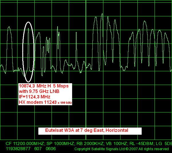
Next paragraphs with specific frequency and symbol rate are subject to change. ??Amended 10 Dec 2007 due to frequency and bit rate changed at the weekend

Your downlink carrier is: frequency 10874.3 MHz, 8 MHz wide, nominal Horizontal polarisation. ??

With your LNB local oscillator set at 9.75 GHz (22kHz tone off) the wanted carrier is at 1124.3 MHz in the cable. (Type 11243 into the modem set up screen, which uses 100kHz steps.)
...

Lacking a Horizon meter or a spectrum analyser is it possible to use the HX50 modem.  Program all the details into the setup screen and use the modem to detect the correct satellite and to peak up.  This will require that you have a laptop PC at the antenna connected to the modem with a long ethernet cable. You need to be able to see when the receiver locks up and drops out as you pass across the satellite and also the signal quality value, which goes up to 100. Using a laptop may be difficult due to the sunlight on the screen.

If you have used the Horizon meter to peak up and you then go indoors and read the signal quality on the modem, expect to see a figure like 90 to 95.

Stick with the single receive cable until you have completed the alignment.

Best regards, Eric.
Back to top
« Last Edit: Feb 7th, 2019 at 4:09pm by Admin1 »  
 
IP Logged
 
Ex Member
Ex Member


Reply #9 - Oct 31st, 2007 at 12:04pm  
Eric,

Thanks for the help on this forum. We were having the same problems as SGT Herrera. We were receiving a good RX signal but the TX would not lock on. After changing the feed horn to your recommendations and rotating the dish for polarization rather than the filter and RF assembley we locked on both RX and TX.

Thanks again,

SFC Taylor
Back to top
 
 
IP Logged
 
Ex Member
Ex Member


Reply #10 - Oct 31st, 2007 at 6:45pm  
Hi Eric,

I wasn't able to do much today and now I am tied up until late tomorrow....

I corrected the feed horn assembly and rotated the dish to 45.5 as instructed. I also adjusted the elevation also as instructed.

Right now, my question is regarding the VSAT specific lat and longtiudes. I am using the stock numbers for LSA Anaconda. I am wondering if I need to stand in front of the dish with a PLGR and get accurate numbers for the dish itself. Everything I am doing right now is based on a wide location. Or is this a non-issue in the grand scheme of things.

My sat meter was pre-programmed by BW, so I should get a lock or FOUND reading.

When commisioning the modem, there is an option during the sat strength reading for "Use Outdoor Pointing Device" or something to that effect. I saw this in a screenshot I have. Might be obvious, but what is the ODP?

One of the setup screens also had VSAT specific lat/longitudes numbers. That's the other reason I was wondering about using my PLGR to get hyper accurate numbers.

Again, thanks for the help.

best,

CH
Back to top
 
 
IP Logged
 
USN - Retired
YaBB Moderator
★★★★★
Offline


Posts: 837
Kentucky (USA)
Reply #11 - Oct 31st, 2007 at 9:24pm  
The outdoor pointing device is more accurately called the outdoor pointing interface - or OPI. But the $100 cost usually restricts it's ownership to the installer community. I touched upon it briefly above, when I mentioned the capability to remote SQF and ACP numbers from the PC (GUI) to the dish (via RX cable). You can do the same thing with a laptop at the dish, or with a helper at the distant PC (shouting numbers as you tweak the dish).

I wouldn't be surprised if someone over there already has one though. It looks like this: ...
Perhaps you can borrow one. If you're on a DVB-S2 gateway, you'll probably need either an OPI-B or OPI-C version.

The numbers provided by the look angle calculators are by no means the end of the job. They're only intended to get your dish oriented close enough to the correct point in space to intercept the desired signal. After that, it's simply fine tuning on the ground.

//greg//
Back to top
« Last Edit: Oct 31st, 2007 at 11:28pm by Admin1 »  

USN (Ret)
 
IP Logged
 
Eric Johnston
Senior Member
★★★
Offline


Posts: 2109
Reply #12 - Oct 31st, 2007 at 11:25pm  
You can find your lat long location here: https://www.satsig.net/maps/satellite-dish-pointing-iraq.htm If you select W3A at 7 east it will also give your the dish pointing angles. Alternatively just step outside with a GPS receiver.

You only need an accuracy of lat long, to 1 minute or 0.01 deg accuracy, so there is no need to stand exactly at the dish. The location makes the range and thus the burst timing correct so you don't transmit bursts on top of someone else.

See Greg's comment above regarding a Hughes outdoor pointing interface. I think should be able to peak up fine with the Horizon meter. Note that peaking up really means that, you have to get to the exact centre of the top of the beam.

Best regards, Eric.
Back to top
« Last Edit: Feb 7th, 2019 at 4:10pm by Admin1 »  
 
IP Logged
 
Ex Member
Ex Member


Reply #13 - Nov 2nd, 2007 at 7:11am  
Eric and Greg,

Quick update. I reconfigured the dish a directed and then went of a mission.

Quite a few things happened in the meantime before I got back.  I had some of our crew work on this project, GPS check, better location, etc.

Last night I had 94 signal strength on the modem but little transmit strength as advised by Ray at BW. It was transmitting, but not usable enough to acvtivate my account. SO I go to bed.

This morning, with nothing changed but a relocation of the modem, I now have 15 signal strength.

I checked the manul commissing window to double check the settings and now the TRANSMIT POL is set to HORIZONTAL and TRANSMIT RADIO is now set to 1 watt and not 2.

I assume the modem commsioned with bad settings. I am waiting to hear from BW, but they are a few hours behind us here in Iraq.

I only have a few more hours before I am back on another mission.  I am hoping this is a somewhat easy error to correct. Maybe a new config upload. Re-register.

Oh...I am also off my 2 minutes on my lat/long....my location shows 44 LONG 23.484 EAST and 33 LAT 56.363 NORTH. So my LONG is off by two minutes. We couldn't get our hands on PLGR or DAGR until last night. All of our GPS' are vehicle mounted.

More frustration, but getting 94 last night shows me that there is light somewhere down the tunnel.

CH

Back to top
 
 
IP Logged
 
Eric Johnston
Senior Member
★★★
Offline


Posts: 2109
Reply #14 - Nov 2nd, 2007 at 8:16am  
If powering off, moving the indoor modem and repowering it, caused the receive signal quality to fall from 94 (excellent) to 15 (no signal at all) the cause may be that the LNB cable has come loose or that the modem has lost its configuration and is no longer tuned to the correct frequency and symbol rate.

The centre pin of an F connector plug should stick out about 2mm. When screwing in, make sure that the pin goes smoothly into the hole and that the outer cable sheath and braid does not get pushed back. The braid must make good connection inside the plug. Power off at the AC wall plug before working on the F connectors.

. Try to get the receive quality back up to 94.

. Note that any power cycling of the modem must be done using the AC mains plug/switch at the wall socket.  The DC connector between the power supply module and the modem must remain connected.

The change in the polarisation display (on the setup/config screen) following commissioning is a spurious display of no consequence.  Ask BW about the 1 watt / 2 watt anomaly.

Tell BW what are your true lat/long coordinates.

Best regards, Eric.
Back to top
« Last Edit: Feb 7th, 2019 at 4:10pm by Admin1 »  
 
IP Logged
 
USN - Retired
YaBB Moderator
★★★★★
Offline


Posts: 837
Kentucky (USA)
Reply #15 - Nov 2nd, 2007 at 11:25am  
Sgt Herrera - Does the top level of your user interface look anything like this?
...
If so, I might be able to help you navigate through it - to include fixing that 1w/2w error.

//greg//
Back to top
 

USN (Ret)
 
IP Logged
 
Ex Member
Ex Member


Reply #16 - Nov 2nd, 2007 at 5:39pm  
Greg, Eric

Thanks for the help. I troubleshot everything at the modem. Connections were solid. Eveything looked good, so I went back up to the dish, now sitting on a large concrete bunker, and lo and behold, I needed to repoint the dish. I think I need to mark the nuts and bolts somehow, because I suspect foul play on this one.

At the modem, I was able to get 95 with Rx code of 5 and Tx of 7 I think. BW activated the account and just before I went on shift, the system was online and functional. But James at BW said my transmit speed was a little low, so I am planning on fine tuning the alignment as soon as I get back tomorrow.

I guess the real test will be when all 13 of us are online at the same time. Ordinarily this won't happen that often, but I am curious to see realtime browsing speed.

When I picked up our dish at DHL, there had been 6 other systems that also arrived. I wonder if any of those people are going down the self-install road.

Ray and James mentioned a bug in the software that would cause the changes in the config of the modem...like the 1 watt instead of the 2 watt selection and the Tx polarisation set to Horizontal. As long as the modem was comissioned initally with the correct settings, then all is well.

Greg-Yes, my System Status page looks very much like yours.

I have definitely learned a lot here and I won't stop just because my system if working. There is always room for improvement! Plus, I may end up buying a system like this for myself later when I get back to the States. I tend to live in mountainous areas were cable is non-existant.

I do wonder about all the dishes I see around here almost pointed in the dirt or directly at nearby buildings. most at ground level.

best,

CH
Back to top
 
 
IP Logged
 
Eric Johnston
Senior Member
★★★
Offline


Posts: 2109
Reply #17 - Nov 3rd, 2007 at 6:50pm  
Quote:
I do wonder about all the dishes I see around here almost pointed in the dirt or directly at nearby buildings. most at ground level.


Satellites dishes need to be able to see the relevent satellite and in many cases, where the elevation angle is sufficient to clear the roof of the next building, a low ground mounting is fine, particularly in military areas where roof mounting may be hazardous. ? Otherwise low ground mounting improves resistance to terrestrial interference such as radar, improves accessibility and reduces wind loading. ?Disadvantages are that people may interfere with the dish or block the beam with vehicles etc.

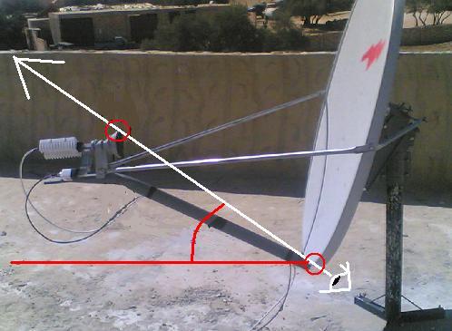
You can roughly assess the beam direction from an offset design dish antenna by putting your head and eye behind the dish near the back end of the main feed arm and sighting just under the edge of the dish and over or just below the top rim of the feed horn circular radome window. ? This is an approximate way to determine if the beam is blocked by a nearby building, as antenna designers arrange for the feed horn to hardly block the beam.
...
A more accurate assessment of elevation is to use an inclinometer and a long strip of wood held by someone else.

Best regards, Eric.
Back to top
« Last Edit: Nov 3rd, 2007 at 9:25pm by Eric Johnston »  
 
IP Logged
 
bentley
Member
★★
Offline


Posts: 7
Reply #18 - Jan 10th, 2008 at 4:10pm  
This is a good point to confirm what Eric is stating here.
When configuring the HX50 modem, as long as the  receive polarisation is set to Horizontal and the Transmit Polarisation is set to Vertical and also 2w is set for the radio head, then these values will be set into the modem regardless of the values displayed after saving.
Back to top
 
 
IP Logged
 
Pages: 1