Advertisment: Broadband via satellite
Advertisment: Worldwide satellite services from Ground Control Company

www.satsig.net

Satellite Internet Forum.

Welcome, Guest.        Forum rules.
      Home            Login            Register          
Pages: 1

TS2 Max signal volts of 4.5v on INTELSAT 10-02 1W

(Read 8295 times)
ahedin
Member
★★
Offline


Posts: 8
Afghanistan
Jun 4th, 2009 at 9:37am  
Hello,

INTELSAT 10-02 1W

I'm trying to get our 1.2m dish aligned and all I'm able to get for signal voltage is 4.5v from the iDirect 3100 dish pointer.

We are located at:

lat.  32 degrees
long 62 degrees

Using these values from the satsig calculator:

elevation=  14.06 minus 17degrees = -3.0 dgrees.
azimuth   251 mag north
polarization    54.6 degrees

Our provider TS2 has been of no real help to resolve this, so any help or ideas on this problem would be greatly appreciated.

Thanks
Back to top
« Last Edit: Jun 8th, 2009 at 11:22am by Admin1 »  
 
IP Logged
 
Eric Johnston
Senior Member
★★★
Offline


Posts: 2109
Reply #1 - Jun 4th, 2009 at 11:33am  
Please say what is the name of your downlink receive polarisation ?.  It will be Horizontal or Vertical

Polarisation:
If Horizontal set your LNB so it is directly upwards.  < edited error corrected.
If Vertical set your LNB so it sticks out sideways.  < edited error corrected.
Then turn the whole feed/LNB/BUC assembly exactly 54.6 deg clockwise, while facing towards the satellite in the sky.

Elevation angle:
The beam elevation required is 14.06 deg.  This is rather low but quite acceptable.  The limit for Ku band is 10 deg.  If 17 deg is the correct offset angle for your dish then the -3 deg means that the top edge of the dish is sin(3) x 130 = 6.8cm forwards from the lower edge. Dangle a thread with a weight down the front and adjust till the gap at the bottom is 6.8cm.  Make sure there is no obstruction, tree, wall etc in the direction towards the satellite.  Put you head/eye behind and just under the dish lower edge of the dish and look at the top edge of the round feed horn window. You should be able to see the sky at 14 deg beam elevation angle.  This is the lower edge of the 1.2m diameter cylindrical beam to the satellite.

Swing the dish boldly sideways around the approx magnetic compass azimuth bearing and the modem demod will lock to the wanted carrier.  Spend at least 30 minutes peaking up to the exact centre of the beam by halving the distance between equally degraded signals either side and above and below the beam. The exact peak is really important.

Best regards, Eric.
Back to top
« Last Edit: Jun 4th, 2009 at 2:11pm by Eric Johnston »  
 
IP Logged
 
ahedin
Member
★★
Offline


Posts: 8
Afghanistan
Reply #2 - Jun 6th, 2009 at 6:48am  
Eric,

Thanks for the reply...but

We moved the dish to a highter location and reset it back up. I still heven't heard back fro TS2 about the LNB polarization as to whether it's horizontal or vertical. We tried it both ways and still can only get a MAX voltage of 5.0v.

We are doing this with the BUC cable discontected as the instructions show. Will it change or make difference  if both cables are hooked ?

My other question if you could help is: If we are getting the wrong SAT signal will it match the readings we get now? Everything we've read states that if we are on the right SAT it will be a noticeable signal...is this a true fact?

I appreciate all your help, but this is very frustrating.

Repectfully,

Arin
Back to top
 
 
IP Logged
 
Eric Johnston
Senior Member
★★★
Offline


Posts: 2109
Reply #3 - Jun 6th, 2009 at 9:11am  
If you are trying both polarisations the two positions to try are:

Horizontal:  Start with LNB at the top, then turn +54.6 clockwise, while facing towards the satellite.

Vertical:   Start with LNB at one side, then turn +54.6 clockwise, while facing towards the satellite.

TS-2 have probably told you what name polarisation to start with and what adjustment angle to then apply.

It is safer to just have the LNB cable connected initially till pointing is completed.  There is no danger of inadvertant transmission.   Power off at the mains before connecting the BUC coax cable.  It should not make any difference when the BUC is connected.  If it does make a difference then the outer sheath braid of the BUC cable may be poor connection.

If you alter the elevation angle, you can probably detect several satellites with small voltages.  Only the wanted satellite will give a big voltage, but you need the modem configured correctly with an options file which sets the modem receive frequency and symbol rate.  If you have clearly found a satellite and it is the wrong one then the other satellites will be in a diagonal line from upper left to lower right (south west).

The model number of the LNB is important as different LNBs have different local oscillator frequences.

TS-2 may have told you what is the satellite frequency, what is the LNB local oscillator frequency and what is the modem tuning frequency.

Satellite freq    = LNB LO freq    + Modem tuning
e.g.
11.111222333 = 10.000000000 + 1.111222333 (all in GHz)

TS2 should have sent you the correct options file for Intelsat 10-02.  The options file sets up the modem tuning frequency, bit rate and FEC type.

Searching this forum for "10-02"  for the last 337 days shows up a number of similar problems.  If you resolve this please can you tell us everything so other people in future may be helped.

Best regards, Eric.
Back to top
« Last Edit: Jun 6th, 2009 at 11:54am by Eric Johnston »  
 
IP Logged
 
ahedin
Member
★★
Offline


Posts: 8
Afghanistan
Reply #4 - Jun 6th, 2009 at 9:47am  
Eric,

Here is what they sent with the intsallation and set-up instructions for the SAT.

INTELSAT 10-02 1W

CENTER FREQUENCY:11093MHZ
SYMBOL RATE :19191
FEC:7/8
RECEIVE POLARITY:HORIZONTAL +52
L-BAND RECEIVING FREQUENCY 1093MHz (IF LO:10GHz)

I see that it's Horizontal +52

We don't have a spectrum analizer so we are doing with a compass and radio's to find it using the iSite dish pointer.

Thanks for your help and will keep trying and YES, we will keep you posted and update our findings once we get it working..

Let me know if there is anything we're missing or overlooked....

Arin
Back to top
« Last Edit: Jun 7th, 2009 at 11:28am by Admin1 »  
 
IP Logged
 
Eric Johnston
Senior Member
★★★
Offline


Posts: 2109
Reply #5 - Jun 6th, 2009 at 11:25am  
If you still can't find the satellite I suggest:

Check the LNB make and model number and make sure it is LO=10 GHz type, in case they have sent the wrong type LNB. e.g.:
10 GHz NJR2784 NJR2184   wanted
10.75 GHz NJR2744 NJR2144 not suitable
11.3 GHz NJR2754 NJR2154  not  suitable

Check the modem options file to see it has the same frequency as per your details above 1093000000, in case they have sent the wrong options file.

When pointing the dish, set the elevation first (6.8cm gap between plumb bob and lower edge), then swing boldly sideways to find the satellite.

Reading more here might help:
https://www.satsig.net/cgi-bin/yabb/YaBB.pl?board=ivsat-me;action=display;num=12...

Best regards, Eric.

Back to top
 
 
IP Logged
 
ahedin
Member
★★
Offline


Posts: 8
Afghanistan
Reply #6 - Jun 7th, 2009 at 8:12am  
Eric,

The LNB has model number NJR2784HH on it.

Question?  Does the pintle point of the LNB away from the BUC or towards it on a lower profile mount?

The LNB mounts so the pintle/doppler is in a straightline with the tube mount. I pulled it off and checked it and the inside of the LNB mount has a beveled edge on one side and a straight edge on the other going inside of the elbow mount for the LNB. Could you clarify the correct mounting position of the LNB.

Regards,

Arin
Back to top
 
 
IP Logged
 
Eric Johnston
Senior Member
★★★
Offline


Posts: 2109
Reply #7 - Jun 7th, 2009 at 10:01am  
A NJR2784HH LNB is suitable for 10.95 - 11.7 GHz satellite frequency input.  The local oscillator is 10 GHz and the output 950 - 1700 MHz.

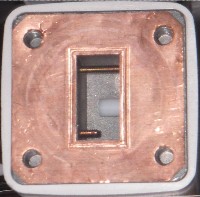
By "pintle point of the LNB" I guess you are referring to the half dipole pin antenna inside the LNB rectangular waveguide aperture.  Such a pin, often with a broadband lump on the end, may be visible when the LNB is detached.
...
The line of the pin is the receive polarisation. In this image the pin is covered with a white PTFE dielectric tube to widen the bandwidth.

If the LNB/filter sidearm is upwards then the pin will be horizontal and the result will be a horizontal polarisation starting position. (then apply the +54 deg clockwise adjustment, viewing towards the satellite).  

When attaching the LNB to the filter arm it is important that the two rectangular waveguide holes are aligned.  It does not matter which side is the pin or other features within the waveguide.

...  ...
Both of these acheive the same result, a horizontal polarisation starting position.

Best regards, Eric.  
Back to top
« Last Edit: Jun 7th, 2009 at 11:17am by Eric Johnston »  
 
IP Logged
 
ahedin
Member
★★
Offline


Posts: 8
Afghanistan
Reply #8 - Jun 8th, 2009 at 8:15am  
Eric,

Thanks for the info and explination.

Having checked the position of the dipole and it is correctly aligned for horizontal polarization.

The dish has been rechecked and rechecked to make sure it's in the correct position, we still can't get more than 4 - 5volt signal. I checked the dish along the diagonal line as you suggested and no change.

The software seems to be reaging correctly with a 1107. mhz L-band receiving reading as you indicated.

Why can't we get any higher readings?  Thanks in advance for your quick reply.

Arin
Back to top
 
 
IP Logged
 
Eric Johnston
Senior Member
★★★
Offline


Posts: 2109
Reply #9 - Jun 8th, 2009 at 9:08am  
Quote:
The software seems to be reaging correctly with a 1107. mhz L-band receiving reading as you indicated.


What is the 1107 MHz?.  You said that it should be 1093 MHz.  If 1093 is correct then the options file should contain:

[MODEM_PARAMETERS]
     rx_freq = 1093000000

I think you have wrong options file or are pointed at wrong satellite.

Best regards, Eric.
Back to top
 
 
IP Logged
 
ahedin
Member
★★
Offline


Posts: 8
Afghanistan
Reply #10 - Jun 8th, 2009 at 10:10am  
In the iDierct information screen it reads as follow

Receive Porperties:

L-Band Freq = 1107.62 MHz
LNB Translation= 1000 MHz
LNB Stability +/- 0.9
Info Rate:     8579.389

Back to top
 
 
IP Logged
 
Eric Johnston
Senior Member
★★★
Offline


Posts: 2109
Reply #11 - Jun 8th, 2009 at 11:06am  
The iDirect modem has been configured with an options file which has different information from that on your email above.
"INTELSAT 10-02 1W
CENTER FREQUENCY:11093MHZ
SYMBOL RATE :19191
FEC:7/8
RECEIVE POLARITY:HORIZONTAL +52
L-BAND RECEIVING FREQUENCY 1093MHz (IF LO:10GHz)  "

Ask TS2 to send you the correct options file as text so you can read it.

Ask them to explain why the modem says 1107.62 and your email says 1093 MHz  

Ask why the modem says 1000 MHz for the LNB translation.  This is wrong; it should be 10000 MHz or 10000000000 Hz.  i.e 10 GHz, the same as the NJR2784HH LNB.

Ask why the modem configured Info rate = 8579.389
is not in agreement with the email that says:
SYMBOL RATE :19191
FEC:7/8

See here for explanation of information rate, fec coding, modulation method and symbol rate.

One or the other is quite wrong.

Best regards Eric.

Back to top
 
 
IP Logged
 
skymoe8381
Member
★★
Offline


Posts: 11
Reply #12 - Jun 9th, 2009 at 4:54pm  
Just saw that your LAT/LONG is close to mine.  We are at 32.93N 69.15E  We were never able to hit Intelsat.  We had them move us to NSS6.  Down side is they only do 1:1 services.  I have two terminals one works great the other never works.  I'm thinking about looking for a new service provider.
Back to top
 
 
IP Logged
 
Pages: 1