Advertisment: Broadband via satellite
Advertisment: Worldwide satellite services from Ground Control Company

www.satsig.net

Satellite Internet Forum.

Welcome, Guest.        Forum rules.
      Home            Login            Register          
Pages: 1

Power calculation for iDirect HUB

(Read 10048 times)
adnabil11
Member
★★
Offline


Posts: 2
Jun 13th, 2011 at 8:52am  
Hi all;

I would like to ask you about my power consumed in Watt as I have 2 carriers:-

1- 1st carrier with Tx power= -9.5dbm
2- 2nd carrier with Tx power= -12dbm

I use 30W BUC, and I need to know the exact power (in Watt) consumed from this BUC.

Regards;


Back to top
« Last Edit: Nov 23rd, 2016 at 4:32pm by Admin1 »  
 
IP Logged
 
Eric Johnston
Senior Member
★★★
Offline


Posts: 2109
Reply #1 - Jun 13th, 2011 at 10:19am  
To measure BUC power output:

You make the measurement using a high loss crossed waveguide coupler and a power meter.
...
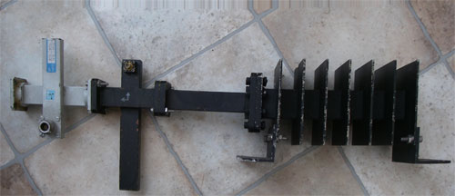
This shows my portable test set up. You connect the Ku band BUC output to the waveguide end on the left. The power goes mainly straight through the guide and is absorbed in the finned dummy load on the right.  You connect a power meter head to the N type connector on the first grey coupler. The calibration is -40.0 dB at 14 GHz and -39.9 dB at 14.5 GHz. Other couplers have other nominal loss, like 50.0 dB.
The second, black, coupler does a similar job and has an SMA output connector for a spectrum analyser.

...
This shows an HP/Agilent power meter head and meter. Read the calibration factor off the table printed on the head, typically values for about 10 spot frequencies between 10 MHz to 20 GHz, including 50 MHz.

...
Set the calibration factor using the table that comes printed on the sensor head for 50 MHz. Calibrate using the 1 mW 50 MHz reference before use.

Connect the power meter sensor head to the N type socket on the waveguide.

Set the calibration factor using the table that is printed on the sensor head for the actual freq, say 6.2 GHz.

The meter may be set to display W, mW, uW or nW or dBm or dB(rel).  Set dBm

Example:
The power meter reading is - 13 dBm.

So BUC Power = -13 + 50 = +37 dBm = 7dBW = 5 watts.

Note that the power reading is the total RMS power, so if you are transmitting multiple carriers it is the addition of all of them.

All the above gives highly accurate results.

Warning 1: Power meters have expensive and sensitive sensor heads.  Be careful not to burn them out.  Make sure you know the maximum input rating and have a suitable high loss coupler or attenuator in front.  

Warning 2: Always terminate the BUC output waveguide, either into the antenna feed system or an appropriately sized  dummy load.  Microwave power heats , and may burn, the human body.  Never look down a waveguide as the power, and even quite low  power, will cook your eye lens, which has no cooling blood supply.

Conversion:

Watts to dBW: 10 log (watts) = dBW
Watts to dBm: 10 log (watts) + 30 dBm

dBW to dBm:  dBW + 30 dBm
dBm to dBW:  dBm - 30 dBW

dBW to watts: divide by 10, =, 10^x watts
dBm to milliwatts:  divide by 10, =, 10^x milliwatts

Try to learn some or all of these:

+20 dBW = 100 watts
+10 dBW = 10 watts
+6 dBW = 4 watts
+3 dBW = 2 watts
0 dBW = 1 watt
-3 dBW = 0.5 watt
-10 dBW = 0.1 watt

0 dBW = +30 dBm

Best regards, Eric.
Back to top
« Last Edit: Nov 16th, 2016 at 5:12pm by Admin1 »  
 
IP Logged
 
Eric Johnston
Senior Member
★★★
Offline


Posts: 2109
Reply #2 - Jun 13th, 2011 at 10:32am  
The only information you give is:

1- 1st carrier with Tx power= -9.5dBm
2- 2nd carrier with Tx power= -12dBm

The first thing I need to say is that you really should try to avoid transmitting multiple carriers.  Are you sure you can't arrange things so that you transmit just one carrier.  You are making big problem and inefficiency for yourself in terms of output back off and intermodulation interference.

If you add the two carriers together the total power is -7.6 dBm.

To do this calculation go to Accessories, Calculator, View Scientific mode.

Take each number in turn and enter is as divided by 10, then do +/- to make it negative

e.g.

-9.5 dBm
enter 0.95
change sign +/-
now reads -0.95
do 10^x
now reads 0.112
Write this down thus
0.112

12 dBm
enter 1.2
change sign +/-
now reads -1.2
do 10^x
now reads 0.063
Write this down below the result above thus
0.112
0.063

Repeat if more than 2 carriers
add up the column of figures thus
0.112
0.063
-----
0.175
do log
result is -0.757

In your head multiply by 10 and the answer is -7.57 dBm.

Best regards, Eric.
Back to top
 
 
IP Logged
 
Eric Johnston
Senior Member
★★★
Offline


Posts: 2109
Reply #3 - Jun 13th, 2011 at 10:56am  
If you know the power into the cable towards the BUC and the combiner / splitter / cable losses you can work out the level at the input to the BUC.

e.g.

TX power at modems = -7.6 dBm
Combiner loss (assume 4 inputs) = 7 dB
Monitor point (-10 dB) splitter loss = 1 dB
Cable loss 10 dB
TX powrer at input to BUC = -25.6 dBm

Assume that BUC gives full 30W (14.8 dBW) rated power output with -20 dBm input.

Power out = 14.8 - 5.6 = 9.2 dBW = 8.3 W.

Note that the gain of the BUC is not known until accurately measured.  Typical specifications allow for a wide range iof variations between different BUCs, different frequencies and temperatures.  Measure yours.

Some BUCs, particularly the high power types, have in built power measurement.  Record the DC current taken and plot this against the measure power output.

If you really need to transmit multiple carriers per BUC you must have a monitor point at the BUC output and a suitable spectrum analyser to plot your output spectrum. Measure the power spectral density of the intermods.

Consider using an extra BUC on the opposite polarisation or an extra antenna with new BUC rather than having two or more carriers per BUC.

Best regards, Eric.
Back to top
« Last Edit: Jun 13th, 2011 at 12:50pm by Eric Johnston »  
 
IP Logged
 
adnabil11
Member
★★
Offline


Posts: 2
Reply #4 - Jun 13th, 2011 at 1:41pm  
Thank you very much for your clarification

Back to top
 
 
IP Logged
 
DGN1
Member
★★
Offline


Posts: 8
Reply #5 - Nov 16th, 2016 at 4:03pm  
Hello Eric,

1) How to assume that BUC gives full 30W (14.8 dBW) rated power output with -20 dBm input? How did you get the -20dBm input and leave 5.6dBm and minus from 14dBW?

2) Did you apply the gain of the BUC as well which is usually 60dB?

Can you provide an accurate calculation please?

Thanks.
Back to top
 
 
IP Logged
 
Admin1
YaBB Admin
★★★★★
Offline


Posts: 1191
Reply #6 - Nov 16th, 2016 at 5:21pm  
I think you are referring to this:

TX power at input to BUC = -25.6 dBm
Assume that BUC gives full 30W (14.8 dBW) rated power output with -20 dBm input.
Power out = 14.8 - 5.6 = 9.2 dBW = 8.3 W.

The gain of a BUC is the difference between input and output.
Input = -20 dBm.
Output = +14.8 dBW = +44.8 dBm.
Gain = 20+44.8 = 64.8 dB.

Assuming you are in the linear region, i.e. at or below the -1dB gain compression point.

If you reduce the input level by 3 dB, e.g.from -20 dBm to -23 dBm
then the output power will reduce from +14.8 to +11.8 dBW = 15.13 watts.

15.13 watts  =  10 ^ (11.8/10)  = 10 ^ 1.18
Back to top
« Last Edit: Nov 17th, 2016 at 10:26am by Admin1 »  
WWW  
IP Logged
 
DGN1
Member
★★
Offline


Posts: 8
Reply #7 - Nov 17th, 2016 at 1:10am  
Hi,

I am getting a wrong outcome, please see below:

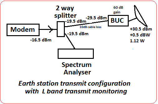
The total input to the BUC is -29.5 dBm (-16.5dBm (Tx Power Output on the modem) - 13dB (WGL)) using Comtech modem.

So according to the provided calculation:

Gain 60dB - Output 44dBm BUC = 16dB Input Gain?

Eric inserted:
BUC input level = -29.5 dBm
BUC gain = 60 dB
BUC output level = -29.5 + 60 = 30.5 dBm or +0.5 dBW


Next is to find out what is the transmit power level from the BUC:

Power out = 14 dBW - 13.5dBm = 0.5dBW = 1.12 W. ?

This is very unrealistic that the 25w BUC might have been transmitting at 1.12W and another 23.88W is a margin, maybe the calculation what I have made is wrong?

Please correct me.

Thank you.

Back to top
« Last Edit: Nov 17th, 2016 at 10:34am by Admin1 »  
 
IP Logged
 
Admin1
YaBB Admin
★★★★★
Offline


Posts: 1191
Reply #8 - Nov 17th, 2016 at 10:13am  
I suspect that the actual gain of your BUC is more than 60 dB, in which case you are probably transmitting something between 2 and 6 watts. 

...

If the NOC is happy with your uplink EIRP then all is well. It is not unusual for a BUC to be operated in clear sky well below its rated power.  You have margin in hand for a 6 dB uplink power control range or for an increase in the transmit bit rate at some future time.

I don't understand "WGL". I think you mean -10 dB of cable loss plus -3 dB splitter loss. If it means waveguide loss then this alters things significantly.  It would be most unusual to have 13 dB of waveguide loss. You should put the BUC much closer to the antenna feed.
Back to top
 
WWW  
IP Logged
 
DGN1
Member
★★
Offline


Posts: 8
Reply #9 - Nov 18th, 2016 at 12:00am  
Hello,

There is still a doubt, if the calculation is correct, then we could have not transmitted 10Mbps with only 1.12W BUC using the provided calculation and additionally have a margin of 23W.

There should be at least 12w according to the LBA as it was approved by the NOC.

Kindly advice if we have been missing something?

The gain is about 60~65dB in case of variation but not more.

Thank you.

Back to top
 
 
IP Logged
 
DGN1
Member
★★
Offline


Posts: 8
Reply #10 - Nov 18th, 2016 at 12:03am  
Also, did you take in scope that Comtech Tx Power Output settings start from "-40" to "0" and our settings set on "-16dBm"

Hope this would help to make an accurate calculation.
Back to top
 
 
IP Logged
 
Admin1
YaBB Admin
★★★★★
Offline


Posts: 1191
Reply #11 - Nov 18th, 2016 at 1:11pm  
You say the Comtech modem output may be adjusted from -40 dBm to 0 dBm. Your setting of -16.5 dB for operation is just fine.  I would not advise a design configuration that involves operation close to -40 dBm or close to 0 dBm as this leaves little scope for later in-service adjustments.

If your BUC gain is 65 dB then the power out is 1.12W x 10^(5/10) = 1.12 x 3.16 = 3.54 W

The link budget analysis will show a required uplink EIRP capability based on satellite assumptions, such as edge of uplink beam, full transponder operation, full nominal interference levels, transponder at low gain setting, end of life minimum satellite output etc. A satellite's actual parameters such as uplink G/T and downlink EIRP may be significantly better than specified, particularly in some locations within the coverage beams and during the early years of operation.  If things deteriorate you may be asked to adjust your power in future as the satellite conditions change.

Assuming your BUC is connected directly to the antenna feed, your uplink EIRP is the addition of the BUC output power and your antenna transmit gain.

Basically you don't have a power meter and want to know how much power your BUC is putting out.

Do you have any telemetry from the BUC that shows what is its power out ?

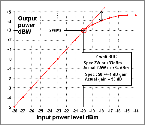
There may be some way you could plot a curve of BUC output power versus output from the modem. With permission from the NOC you could turn your modulation off and reduce the modem output power from -16.5 dBm to say -36.5 dBm in 2 dB steps while measuring your own carrier on the downlink using your spectrum analyser.  Hopefully the graph of carrier power (BUC output) (y axis) and modem (x axis) would be a straight line.  Increasing the level above -16.5 dBm needs NOC permission but I would not rule this out. Ask.

If you are not allowed to go up, the reason will be that your higher power would overload (i.e saturate) the transponder and cause all the other users of the transponder to lose service. You may also cause unacceptable interference (with your CW carrier) to users on the opposite polarisation on the same satellite and to users on nearby satellites around the orbit.

If you are allowed to go up, do it cautiously in 1 dB steps and plot the graph as you do it, extending the straight line upwards. When the line curves over and the vertical gap to the extended straight line is 1 dB, stop. You have reached the -1dB gain compression point. If you go further you risk damage to the BUC but it will eventually reach its saturated output power, which may be 25 W or more.
If you can measure the DC input volts and current to the BUC while doing all this, then a graph of that may help also.

...
This transfer characteristic curve for a nominal 2W BUC shows the idea.

I do recommend getting a calibrated high loss cross-waveguide coupler and power meter.  Look on eBay for HP/Agilent  power sensor head and meter. The old analogue ones work perfectly well.


Back to top
« Last Edit: Nov 23rd, 2016 at 4:33pm by Admin1 »  
WWW  
IP Logged
 
Pages: 1