Advertisment: Broadband via satellite
Advertisment: Worldwide satellite services from Ground Control Company

www.satsig.net

Satellite Internet Forum.

Welcome, Guest.        Forum rules.
      Home            Login            Register          
Pages: 1

Net not activated x3

(Read 6613 times)
Habib D
Member
★★
Offline


Posts: 7
Sep 30th, 2014 at 12:07pm  
Dear,

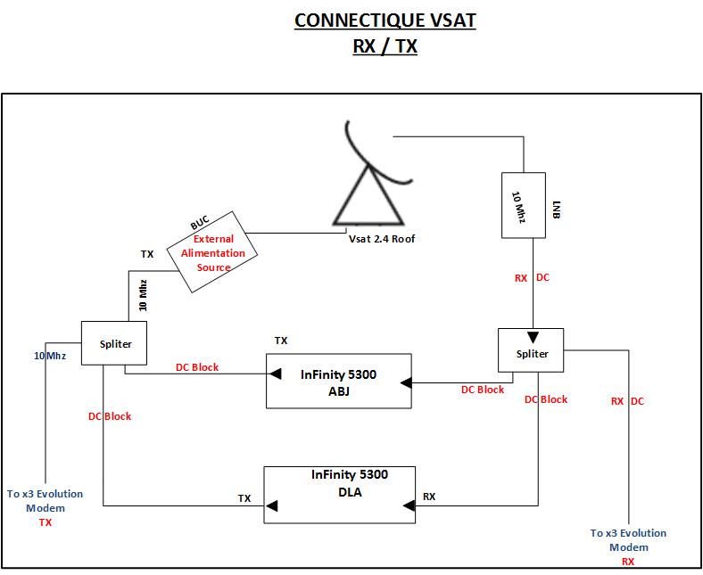
I'm planning to share a single antenna with infinity 5300 and x3 Evolution  Modem.
Before my integration, i made the test with each modem on the antenna. All of them work correctly when connected to the antenna.
I then connected all the modem behind the splitter/combiner. The Infinity modem is working fine but this is not the case for the x3 modem (RX ON, TX ON, NET not activated). It seem that the Hub doesn't get the burst from the x3 Evolution.

What do you think i missed.

You will find a sample of what i'm tryning to achieved in the photo
Back to top
 

RF_connection.jpg (38 KB | 261 )
RF_connection.jpg
 
IP Logged
 
Admin1
YaBB Admin
★★★★★
Offline


Posts: 1192
Reply #1 - Sep 30th, 2014 at 3:25pm  
The BUC power rating needs to be nearly twice the power of 3 simultaneous transmit signals, all at max uplink power control level, to keep intermodulation interference acceptable.  If the maximum powers under rain condition are 5, 5 and 5 watts then the total power is 15 watts and you need something like a 25 watt BUC (-2dB back off).
Back to top
« Last Edit: Sep 30th, 2014 at 10:46pm by Admin1 »  
WWW  
IP Logged
 
Habib D
Member
★★
Offline


Posts: 7
Reply #2 - Sep 30th, 2014 at 4:18pm  
Hi Admin1,

Thank you for your availability and your  feedback.
I'm using a 20 Watts BUC according to the Vsat Operator Link Budget.

My main concern here is that, when i connected the x3 modem behinnd the combiner/splitter, it's not working. This is not the same problem with the infinity, nevertheless, both of them have the same RF Specification.
Back to top
 
 
IP Logged
 
Admin1
YaBB Admin
★★★★★
Offline


Posts: 1192
Reply #3 - Sep 30th, 2014 at 11:02pm  
I'm presuming that the two 5300 modems are operating SCPC and have their 10 MHz TX references switched off.

Note that most high power BUCs will give an alarm and stop transmitting if the 10 MHz is absent.

The X3 modem presumably has its TX 10 MHz output switched on.  Is this 10 MHz getting to the BUC?.  Try removing the splitter.  Does the X3 then work OK ? What level does it output ? Should be about 6 dB lower, due to no splitter loss.
Reinsert the splitter but without the 5300's connected. Does the X3 work ? Has its level increased by 6 dB (compensating for splitter loss) ?

What are the three centre frequencies of the transmit carriers?.  Call them A,B and C.  The 3rd order intermodulation interference products work out at all permutations of A+B-C.  Maybe you are interfering with your own carriers (and others on the satellite). With three simultaneous carrier through the BUC you need to be very careful with levels. What happens if you reduce the two 5300 carriers by 3 dB ?.

If your splitters are 4 port then the unused spare port should be terminated in 75 ohm resistor.

Best regards, Eric.
Back to top
 
WWW  
IP Logged
 
Habib D
Member
★★
Offline


Posts: 7
Reply #4 - Oct 1st, 2014 at 8:10pm  
dear,

You would find answer for the questions below.

I'm presuming that the two 5300 modems are operating SCPC and have their >10 MHz TX references switched off.

Yes, this is the case


Note that most high power BUCs will give an alarm and stop transmitting if the 10 MHz is absent.

The X3 modem presumably has its TX 10 MHz output switched on.
Yes, it is activated

Is this 10 MHz getting to the BUC?.
Yes,


Try removing the splitter.  Does the X3 then work OK ?
Yes the x3 work without the splitter

What level does it output?
Don’t get this question (transmit power is – 27)

Should be about 6 dB lower, due to no splitter loss.
Reinsert the splitter but without the 5300's connected.Does the X3 work ?
Not working, RX and TX ON, but x3 don’t get into the network


What are the three center frequencies of the transmit carriers?.  Call them A,B and C.

A (5300):6197.766
B (5300):6197.182
C    (X3): 6196.2062
Back to top
 
 
IP Logged
 
Admin1
YaBB Admin
★★★★★
Offline


Posts: 1192
Reply #5 - Oct 2nd, 2014 at 8:11am  
If the X3 modem output level stays the same, at -27 dBm, when the splitter is inserted, then the burst transmit level will be reduced by about 6 dB and the burst will be too low to be received at the hub. The hub should have measured the burst received level at the hub and told you, and adjusted the level as appropriate.

When an X3 is commissioned, the hub sets a maximum modem output level in the hub database, corresponding to the P-1dB output of the BUC or the maximum allowed EIRP, whichever is the lower.  Ask the hub to check all your transmit levels and maybe adjust the maximum value for your modem output.  The hub should be watching your transmit TX levels very carefully as there is great risk of you causing intermodulation interference to other services.

When you transmit more then one carrier via a BUC, significant intermodulation products are created if the composite power of the carriers is near to the BUC power rating.  If you back off the BUC by say -2 dB, the intermodulation products may be reduced to an acceptable level.  -2 dB output back off means that three 5 watt carriers need a 24 watt BUC.

...
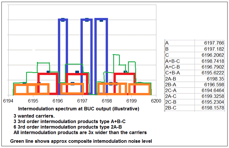
This spectrum drawing illustrates the results of 3 carriers, A, B and C.  The red intermodulation products are of type A+B-C.
the orange intermodulation products are type 2A-B. The green line shows the composite intermodulation noise spectrum. Note that the intermodulation interferes with other carriers on nearby frequencies in the transponder.

The sharp cornered rectangles shown are illustrative only.  Real digital carriers have rounded corners and the shape of real intermodulation products have very rounded corners and the composite spectrum of the intermodulation is a wide, rounded form, with a number of humps.

Best regards, Eric. 
Back to top
« Last Edit: Oct 2nd, 2014 at 10:29am by Admin1 »  
WWW  
IP Logged
 
sridhar
Member
★★
Offline


Posts: 7
Reply #6 - Oct 3rd, 2014 at 4:22pm  
Habib
Increase the transmit power level of the x3 modem. This increase should be equal to the insertion loss of the splitter. for example if  the loss is 6 dB in the splitter, increase the transmit power of x3 by 6 dB. Ofcourse take care that you are not saturating the BUC/RFT  and also sufficient power margin in the BUC/RFT.Hope this works.
Back to top
 
 
IP Logged
 
Habib D
Member
★★
Offline


Posts: 7
Reply #7 - Oct 4th, 2014 at 11:59am  
Hi Eric,

Beyond the problem i'm facing, your post is very usefull, i get  more understanding on RF. Where do you think, i could find the tools in order to show up this intermodulation.

Sridhar, i increased the power without any success.

I opened a ticket, and for iDirect's TAC it's not possible to share on the same ODU iSCPC and TDMA.

What do you think about this.

Regards.
Back to top
 
 
IP Logged
 
Admin1
YaBB Admin
★★★★★
Offline


Posts: 1192
Reply #8 - Oct 4th, 2014 at 4:47pm  
To see the intermodulation products produced by your BUC, you ideally need a high loss crossed-waveguide coupler (e.g. about -50 dB) between the BUC and the feed. Connect a spectrum analyser (with an adequate frequency range) and plot the entire spectrum from say 5.925 - 6.425 MHz, plus the local spectrum around your transmit carriers.  Often the satellite operator will insist on this for any earth station transmitting multiple carriers via a single BUC. Spurious transmissions and IM products are measured.

If you don't have such test facilities, the hub needs to attempt such measurements, which are difficult if there are many other carriers present in the transponder. Other people are likely to report interference hours or days later and it becomes hard to identify the origin if several people have been adjusting their services meanwhile!

I can understand the iDirect TAC saying that is it not allowed to have iSCPC and TDMA in the same BUC. It may be that is technically not possible also.

One valid method of measurement is to make all your carriers CW and change their frequencies so they are very close together, all well within the bandwidth of one of your intended operational carriers. The IM products may then be seen and measured and the carrier levels adjusted.  You must always have the composite BUC power well below (e.g. about half or -3 dB) the power rating of the BUC. This is called "backed-off" and wastes a lot of the BUC power and cost, which is why multi-carrier operation is avoided unless really necessary. This applies to both earth stations and satellite transponders.  Some manufacturers sell 'linearised' BUCs or HPAs which allow operation nearer to saturation, to save both power and cost. Higher power BUCs often have a built-in broadband power meter to allow  you to monitor the output power.

Get help from your iDirect hub. They will be able to see the transponder spectrum clearly and can measure your carriers.  They also control your X3 power setting using the iDirect hub software.
Back to top
 
WWW  
IP Logged
 
Habib D
Member
★★
Offline


Posts: 7
Reply #9 - Oct 10th, 2014 at 3:20pm  
Hi Eric,

Based on an advice of someone from iDirect, I  have activated the 10mhz reference, on all of my modems rather than have it activated only on one modem.
the x3 modem get into the network.... Grin

Thank you all for your assistance. Special Thanks to Eric.

Tongue Don't ask me, why it's working in that configuration. I really don't know. If somebody have an explanation i will be glad to have it.
Back to top
 
 
IP Logged
 
Pages: 1