|
|
Satellite uplink power flux density (PFD)
This is a calculated result and you will need to adjust your uplink earth station transmit power (and possibly uplink earth station size) to obtain the exact figure you require at the satellite height.
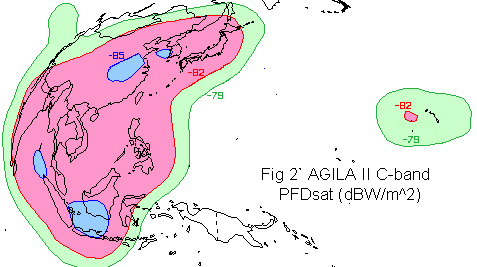
Example PFDsat contours -85 dBW/m^2 to -79 dBW/m^2
The figure you require may be derived from the power flux density to saturate the transponder (pfd/sat) . This figure is available from the uplink coverage map and the satellite transponder specification. See example above.
For example the pfd/sat at beam centre might be -85 dBW/m^2. The pfd/sat on the -3dB contour would then be -82 dBW/m^2. ( Note that the pfd/sat figures can be altered by commanding changes in the gain setting of the satellite transponder, for example in the range -87 to -73 dBW/m^2 on the -3 dB contour. It may be possible to negotiate changes in gain setting, particularly if you lease a whole transponder)
The figures above refer to a whole transponder. If you transmit an uplink signal with sufficient power to produce the pfd/sat specified above you will saturate the transponder. This is applicable only if you are using one carrier in the transponder. In such a case the input and output back offs would both be zero.
For two carriers an input back off of 0.5 dB is suggested, with an output back off of about 1.5 dB due to the production of second order intermodulation products (A+B) which are hopefully absorbed in the satellite before the output filter.
In many cases 3 or more carriers are transmitted through the transponder and
to avoid unacceptable intermodulation interference levels it is necessary to
operate the transponder backed off. Typical transponder operating
points are:
Multi carrier: -6 dB input back off
and -3.2 dB output back off, C/intermod= 21 dB. *
Multi carrier: -10 dB input back off and -4.5 dB
output back off, C/intermod= 21 dB. **
* ** not the same satellite.
The satellite specification will provide a table or graph of input versus output values plus the carrier to intermodulation ratio curve. Transponders with linearisers (e.g. * above) allow operation nearer to saturation while keeping intermodulation acceptable. Intermodulation worse than 15 dB starts to impact on the link budget, 18 to 21 dB is about optimum and 25 dB is too good and you are not making proper use of the downlink power available. The C/IM ratio changes at twice the rate of change of input back off.
Let us assume -10 dB input back off, for multi-carrier operation and carrier to intermodulation = 21 dB.
So for beam edge operation, actual operating pfd is -79 -10 = -89 dBW/m^2. Remember this still applies to the whole transponder.
If the transponder bandwidth is 36 MHz and we want to operate in a 2 MHz wide slot the operating power flux density for this 2 MHz bandwidth is -89 -10 log(36/2) = -101.5 dBW/m^2.
You can't just put this in the link budget. You need to adjust the uplink earth station power (and possibly uplink earth station size) so that this required uplink pfd is achieved. Adjust to make the result equal to -101.5 dBW/m^2.
If you have come from the link budget page, you can go back to it and not lose any figures you have inserted by clicking on the BACK button now.
|
► Page started 2015; Amended 14 August 2023 Copyright Satellite Signals Limited © 2015 all rights reserved. |