|
Focal length of parabolic dish |
Dish interference: Site shielding |
This page explains how to adjust the antenna sub-reflector to get the dish into focus and minimise side-lobe pattern peaks.
Checking the antenna
Since you will be working on new antenna check a few things.
Look at the structure overall and verify that it is complete and that major
parts are not missing and that foundation bolts are tight etc.
Test the drive system cautiously while next to the dish so you can stop
immediately if it does not sound right, the motors start to seize up, or parts
begin to bend etc. Wear a hard hat in case of falling loose parts, rivets,
nuts, bolts, shims, tools etc. Lack of any grease in the drive
screws, no oil in motor gearboxes, seized up main bearings with the wrong shims,
end fittings that are at the wrong end and don't allow full freedom of movement,
brakes stuck on etc are all possibilities. Watch out for cable and
wave-guide loops that are too small and try to stop before snapping the motor
drive cables !. If safety rails are installed they may block free
movement. Each drive mechanism should have software limit stops to prevent
excessive movement. These should be backed up further out with limit
switches (e.g. heated micro-switches). Finally, some distance even further
on, there should be strong end stops that prevent the screws coming out and the
dish falling down. It is better to burn out a motor than drop the dish.
Testing all these needs doing with great care and may take several days if the
antenna is slow to move and lots of rework and re-adjustment is required.
I like to drive the antenna into each micro-switch three times and expect it to
stop well before the mechanical limit every time.
Spectrum analyser set up
Find a stable high spectral density signal to look at. If you have an LNA or phase locked LNB then your frequency stability will probably be good enough for you to use a beacon signal, which is preferred. If you are using an unstable DRO type LNB then you are probably better off looking for a high spectral density digital carrier, e.g. TV. Choose a satellite close to the representative operating elevation angle. Make sure that you are looking at a signal with a polarisation type that matches your receive system. i.e. if you have a linear polarisation system then use a linear polarisation beacon or linear polarisation traffic signal.
Whatever, you need preferably 23 to 35 dB carrier to noise ratio as you are wanting to measure the first side-lobe which will be typically 15 to 25 dB below the main beam. If you are looking at the two first side-lobes, at 18.1 dB and 18.2 dB down, you need to be able to measure them clearly and a C/N ratio of about 18 + 5 dB is just about adequate to do this.
On the spectrum analyser decrease the resolution bandwidth to try and get the C/N up into the 25-35 dB range if possible. With a beacon, 1 kHz - 30 kHz is often about right. For a TV carrier varying the resolution bandwidth will not make any difference, try 100 kHz. Make sure peak hold and video averaging are both OFF. Watch the signal for five minutes and observe for any frequency or level drift. You must have a stable system that does not drift in the time it takes the motors to move the antenna across the satellite, which can be up to 15 minutes on some large slow drive dishes.
First you need to get a clear understanding of the testing method. Always plot the beam patterns while moving the dish one way. In azimuth drive the antenna left to right, while facing the satellite. In elevation drive it upwards. This means that all your recorded pattern plots will be the same and you will never get confused as to which way you were turning the dish when you made that pattern measurement.
Connect up the plotter and make sure you have good pens with plenty of ink, also plenty of sheets of blank paper and a pen. Get yourself really comfortable if possible with hat, warm clothing, cushions, lighting, heat, food and hot drinks if necessary. You must have the antenna drive switches, the azimuth and elevation encoder readouts and the spectrum analyser in one place and this may be right up at the back hub of the dish in a freezing cold wind on top of an office block in Moscow.
You need two relevant spanners, ladder, safety climbing rope etc. A torch is useful, as you may be at it all night. Helpers with food and hot drinks is good.
Practice with the spectrum analyser and plotter. Set to zero span and set the sweep of say 60 seconds and single sweep mode.
Doing the antenna pattern measurements
Drive the antenna left and watch the main beam level drop, go
past the first null and first side-lobe peak and then stop maybe 5 dB down
beyond the first sidelobe peak. Write down the the azimuth and elevation
encoder positions. This is the azimuth start position. Then start
the drive motors to the right and press single sweep start. Wait till you
have the full pattern and then stop the azimuth motor. If all goes well
you will have pattern like that below:
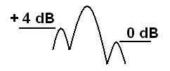
If you have a very big dish the satellite has probably moved by now and and main beam reading will be low. Don't worry about this, you can't miss the first side lobe ring and those measurements are good. Write 0 dB against the lower level side-lobe and the relative value against the higher level sidelobe i.e. + 4 dB. Note that the +4 dB sidelobe came first and is therefore on the leading side of the dish main beam, ie. on the right hand side, looking towards the satellite.
Now drive the antenna back to the satellite and then go down in
elevation to about -5 dB beyond the upper first sidelobe ring. Write down the the
azimuth and elevation encoder positions. This is the elevation start
position. Drive the antenna upwards and plot the elevation cut.
If all goes well you will have pattern like that below. Write
0 dB against the lower level sidelobe and the relative value against the higher
level sidelobe e.g. + 3 dB
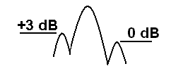
Note that the + 3 dB sidelobe came first so the high part is above the main beam, as you were moving the beam upwards in elevation (I hope).
Now consider just where is the high part of the first sidelobe
ring. Go and stand in front of the dish, looking at it and note that the
high part in the first sidelobe ring is in the top left area, where the arrow
points.
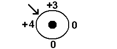
Assuming the dish is Cassegrain, the task is to now push this high sidelobe down by tilting the sub-reflector so that the top left edge goes in towards the main reflector. Assuming 4 bolts, make an adjustment of one full turn on two bolts so as to adjust both elevation and azimuth simultaneously.
The reason for choosing one full turn is that it is useful to
learn what is effect of one full turn. Repeat the antenna pattern
measurements and come up with a new diagram:
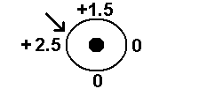
This tells us that 1 turn causes approx 1.5 dB change in relative level. Also that the problem remains in the same general area of the sub-reflector. The top left needs to go in further. Now we can estimate the amount of movement needed. The top need to go a further 1.5 dB or 1 whole turn. The side need to go 2.5/1.5 turns or 1.66 turns or 1 turn and 4 flats. Note that 1 turn equals 6 flats of the nut.
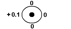
This is near perfect and acceptable.
If you have a Gregorian antenna then instead of pushing the peak of the first side lobe ring down by moving that side of the sub reflector towards the dish you need to think in terms of weakening the sidelobe by raising the edge nearest to the peak.
Sub-reflector adjustment
Note carefully how the sub-reflector is held in position.
If there are three bolts holding the sub-reflector, e.g one at the top and
two on either side at the bottom note how:
Moving the top bolt will tilt the sub reflector in elevation.
Moving the bottom two bolts simultaneously in opposite directions will result in
azimuth tilt, without introducing any focus change.
Moving either of the bottom bolts alone will result in the diagonal tilts.
Moving any single bolt will cause simultaneous tilt and focus change.
If there are four bolts, before making any adjustments it is suggested that one bolt be freed off in both directions, say by loosening the two nuts each by two turns, so that adjustments may be done while the sub-reflector is held with three bolts and using three adjustment bolts only. The spare bolt can then be tightened very carefully (with zero sub reflector movement) as a redundant security fixing, at the end when all is correct.
There are two possible configurations of four bolts holding the sub-reflector:
Two at the top on either side and two on either side at the bottom note:
Assume that the bottom right bolt is completely loosened.
Adjusting the top right bolt will result in azimuth tilt.
Adjusting the bottom left bolt will result in elevation tilt.
One at the top, one on each side and one at the bottom note:
Assume that the bottom centre bolt is completely loosened.
Adjusting the top centre bolt will result in fast elevation tilt.
Adjusting a side bolt will result in diagonal tilts.
Antenna focus adjustment
Once you have the first sidelobes reasonably balanced the next task is to focus the dish by moving the sub-reflector bodily in or out. This can be done by adjusting all the nuts so as to move the whole sub-reflector in or out. Adjust for low sidelobe levels and for deep nulls between the sidelobes. Look between the first and second sidelobes. So when measuring the patterns for focussing use a wider angle sweep than above so you can seen both the first and second sidelobes. A better carrier to noise ratio is helpful like 35 dB so you can see the nulls clearly.
Try to go through the beam peak if possible so that the level of the sidelobe relative to the main beam may be measured. The depth of nulls is a more reliable measurement as you can't miss going through the sidelobe peak, which is ring.
Start with a whole turn on all the nuts and see what happens. If there is an improvement continue moving the sub-reflector in the same direction.
Inevitably after making a number of antenna focus adjustments you will need to readjust the tilt of the sub-reflector.
Note that some antennas have first nulls that are not particularly good but better nulls between the sidelobes 1 and 2. High efficiency antennas have shaped sub-reflectors that distribute the power evenly across most of the main dish surface with a rapid edge taper in the power density towards the edges. Since the nulls between the main beam and the first sidelobe are of no important to interference to other satellites, try when focussing to reduce the level of the 2nd and further out sidelobes. Correct focussing will also give the best gain and highest G/T.
Back to help with setting up satellite dish pointing and alignment page.
An example of my work (Dec 2005, mid winter in Asia, 9m dish)
As found:
First sidelobe differences: Elevation 1.9 dB Azimuth 1.2 dB.
Average sidelobe null: -13.4 dB.
Worst null: Elevation upper null non-existent.
Adjustments:
Top nut: Sub-reflector moved out by 6 turns.
Bottom right nut: Sub-reflector moved out by 3.5 turns.
Bottom right nut: Sub-reflector moved out by 4.25 turns.
Note: As viewed facing into the main reflector.
After adjustments:
First sidelobe differences: Elevation 0.0 dB Azimuth 0.1 dB.
Average sidelobe null: -18.83 dB.
Worst null: Elevation upper -7.5 dB.
|
Page started 27 Nov 2004, amended 25 Feb 2022, 26 Nov 2024. |