Satellite Internet forum
https://www.satsig.net/cgi-bin/yabb/YaBB.pl
Service Providers >> Satellite Internet - Europe >> BUC status
https://www.satsig.net/cgi-bin/yabb/YaBB.pl?num=1530018276

Message started by O.B on Jun 26th, 2018 at 2:04pm

Title: BUC status
Post by O.B on Jun 26th, 2018 at 2:04pm
Hi, I've been working with an iDirect 5000, mainly through telnet.

On the back panel there is a light called BUC PWR, and in the iSite software there is a section called BUC status. These seem to be related, if BUC status = Ok the light is on, if BUC status = Fail the light is off.

I just cannot find a command to check the BUC status/PWR via telnet.

Any help would be much appreciated.

Thanks

Title: Re: BUC status
Post by Admin1 on Jun 27th, 2018 at 10:04am
I believe...

Meaning of Rear Panel BUC PWR LED Indicator:

OFF Indicates that the BUC power is not being supplied.
GREEN Indicates that the BUC power (+24 VDC or +48 VDC) is being supplied.
RED Indicates a BUC problem or an IFL disturbance.

telnet commands:

Try help  This might list all possible commands.

telnet commands for older iDirect iNFINITY routers. Might work? :

tx ifl10 = Show or Set Tx IFL 10MHz
tx iflDC = Show or Set Tx IFL DC Power
tx power = Show or Set Transmit Power Level

For the tx ifl10 or tx iflDC you may add "on" or "off" and change the status.

For tx power you may add a figure and set a new transmit level. I have no idea what figures to use, sign ? dBm ??.

I don't know if it is possible to measure the BUC current. Maybe the BUC RED rear panel LED lights if the IFL cable or IFL connectors are open circuit or short circuit.

We would be interested to hear what you discover.

Best regards, Eric.

Title: Re: BUC status
Post by O.B on Jun 27th, 2018 at 1:10pm
Hi Eric, You are completely right with the BUC PWR LED. Compared with documentation I've found.

I tried alot of commands from typing "help" and I also found a pdf with every command with occasssional descriptions, but no luck so far.

https://www.livewire-connections.com/sites/default/files/files/documents/Hardware_iDirect_Basic_Console_Commands.pdf

I'm using the command tx iflDC to turn the Led on and off. But it doesn't prevent turning on if the the BUC status fails (LED doesn't turns on).

It was suggested to me that the command rxdiag txcurrent effects it. The tests i tried found this:

BUC OFF = BUC Status Ok
BUC ON && Current < 0.22 = BUC status fail
BUC ON && Current > 0.8 = BUC status Ok

I couldn't get the value between 0.22 and 0.8.

I then asked a colleague on the results they found and they got something completely different.

Current < 0.02 = BUC status Ok
Current > 0.03 = BUC status Fail

I'm not sure if rxdiag is to do with the BUC, I can't find any documentation.

Thanks for your time

Title: Re: BUC status
Post by Admin1 on Jun 27th, 2018 at 1:53pm
from the iNFINITY list

rxdiag rxpower Rx RF Composite Power E
rxdiag rxvoltage Rx IFL DC Voltage E
rxdiag temperature Board Temparature E
rxdiag tx10M Tx 10M output E
rxdiag txcurrent Tx IFL DC Current E
rxdiag txpower Tx RF Composite Power E
rxdiag txvoltage Tx IFL DC Voltage

The rxpower Rx RF Composite Power figure might be the entire broadband (950-2150MHz) receive power coming in on the cable, which is useful for initial pointing to detect satellites, like low cost simple satellite TV signal meters.  You get such power from the LNB noise floor and also from any and all satellite. Maybe is it what shows in yellow before you get carrier lock and it goes green.

The txpower Tx RF Composite Power is presumably only applicable when the router is transmitting a steady SCPC carrier.

If you don't see any BUC data (for modern 5000 type router) then since rxdiag is a valid command I suggest trying txdiag to see what happens.

It is important that all 4 connectors on the IFL cables make good connection of both braid and inner conductor.

Some very strange things can happen in one of the braids is open circuit, as DC current can return via the wrong cable and cause voltage drop.

When the  BUC transmits a burst the BUC DC power used  normally increases significantly and low IFL DC resistance becomes important. The current may be taken in the form of high current pulses if a switch-mode PSU is incorporated in the BUC. 

Best regards, Eric

Title: Re: BUC status
Post by O.B on Jun 27th, 2018 at 3:11pm
No such luck with txdiag. I thought it would be a commmand but apparently not.

I think the power of the BUC should increase as well. So if Power = Volts * current, so then if current is more, power will be more. This doesn't work for the second lot of test data. Unless maybe it's receiving too much power?

The testing we did was with tampering the connectors to get fail results, we also tried with 9 BUCs (3 different models) to try and find a correlation.

Think I'm going to have do run some more tests.

Title: Re: BUC status
Post by Admin1 on Jun 28th, 2018 at 11:56am
Regarding the DC power supply to the BUC. If you read the spec for the BUC it may indicate that it is tolerant to a range of DC supply voltages. In which case it will have internal power converter. The current taken via the cable is likely to noticeably increase when the BUC is transmitting a steady carrier, unless the transmitted RF power is very low.

For example, the DC current may be 1 amp when idle and increase to 1.5 amps at maximum BUC RF output.

If the RF transmissions are occasional short bursts then it becomes difficult to detect any changes in the BUC DC supply current.  If the RF bursts are at high power then higher supply current is needed for brief periods.

If you are having problems in the transmit direction to the hub and think that you may be already transmitting at maximum power then consider this...

You are supposed to start transmitting at low power and increase till the hub achieves lock on your signal. The hub software will then tell your router to adjust its tx power upwards till the level into the hub becomes correct.

If you inadvertently transmit too much power initially, perhaps by saturating your BUC at its maximum output capability then your signal can be distorted so that even if it is very high power at the hub the hub receiver thinks it is poor quality (high error rate). The hub software then tells you to increase power further which makes matters worse.

Start again with minimum router output power -35 dBm and increase cautiously in 3 dB or 1 dB steps. Max is +7 dBm I think ?

In service, the hub should dynamically adjust your router output power to keep traffic levels into the hub steady at the correct value, during rain etc.

Title: Re: BUC status
Post by O.B on Jun 28th, 2018 at 4:05pm
I tested changing the TX Power, but I didn't find it very useful so I didn't include it. Here it is:

BUC Ok:

     TX Pwr          Volts     Current
     -35              23.52      0.93
     -34              23.52      0.96
     -33              23.52      0.96
     -32              23.52      1
     -31              23.52      1.05
     -30              23.52      1.13
     -25              23.41      1.45
     -20              23.29      2.2
     -15              23.19      2.49
     -10              23.19      2.57
       -5              23.19      2.59
        0              23.08      2.67
        5              23.19      2.66

BUC Fail:

     TX Pwr        Volts      Current
     -35              23.73      0.2
     -34              23.73      0.2
     -33              23.73      0.2
     -32              23.73      0.2
     -31              23.73      0.2
     -30              23.73      0.2
     -25              23.73      0.2
     -20              23.73      0.2
     -15              23.73      0.2
     -10              23.73      0.2
       -5              23.73      0.2
        0              23.73      0.2
        5              23.73      0.2

This helped to support my first hypothesis. Other than that it didn't show me anything. (Only tested with one BUC)

Title: Re: BUC status
Post by Admin1 on Jun 28th, 2018 at 10:30pm
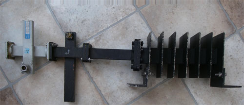
If you test a BUC like that you should terminate the output via a calibrated cross-waveguide coupler to a suitably rated dummy load.

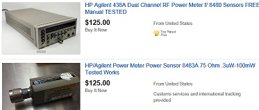
Use a power sensor and meter to measure the output power as you increase and stop when you reach the rated output.


See https://www.satsig.net/cgi-bin/yabb/YaBB.pl?num=1265438382
Note the two warnings about burning out the power meter sensor and the hazard to the human body and eye from microwave radiation.

If you drive the BUC beyond its rated output you may cause partial or complete failure by damaging or burning out the power output stage transistors.

Don't do such tests when pointed at a satellite as you will cause interference.


Title: Re: BUC status
Post by O.B on Jul 2nd, 2018 at 10:04am
When we ran this test we did all the safety stuff. Marked a radiation zone and stayed clear. We also aimed away from the satellite belt to avoid causing any issues to anyone else. I was also told the BUC could go to the power without any issues.

You are right though, I probably should have mentioned these warnings before in case anyone happened to come across this and attempt to replicate.

Title: Re: BUC status
Post by FUGHAR on Aug 25th, 2023 at 1:47pm
Hi,
Please what command can I use to check Tx voltage and Tx current of a BUC
I have tried several commands including tx IFLDC voltage but no headway. Likewise the rxdiag while txdiag not a recognizable command.

Thanks for your time
[#quote]

Title: Re: BUC status
Post by Admin1 on Aug 25th, 2023 at 4:14pm
What model of iDirect router do you have and what model of BUC ?
I hope someone can help you.

Best regards, Eric.

Title: Re: BUC status
Post by FUGHAR on Aug 26th, 2023 at 4:18pm

Admin1 wrote on Aug 25th, 2023 at 4:14pm:
What model of iDirect router do you have and what model of BUC ?
I hope someone can help you.

Best regards, Eric.


Hi,
Thank you for your response. I use X3 & X7 model of the i-direct and C-band BUC Model: NJT5669F.
Thank you.

Regards
[#Quote]

Title: Re: BUC status
Post by Admin1 on Aug 26th, 2023 at 8:51pm
Some characteristics of the NJT5669F BUC:
RF output power: +37 dBm (at -1dB gain compression point)
Gain: 61 dB
DC volts: +24V (+15V to +30V) DC
DC power: 48W max
Mute (therefore no output power): LO unlocked or no 10MHz reference
LED indicator: Green = LO locked. RED: LO unlocked or no 10MHz reference
Note: No mention of any telemetry.
Is the BUC LED showing green ?  Is the 10 MHz reference supply activated ? Is there anything in the IF cable that is blocking 10 MHz?

I don't know if the X3 or X7 modem have the ability to measure the DC volts and DC current being fed to the BUC.  If anyone can help please say here.

Meanwhile you might consider making up a test rig with male/female F connectors and a resistive tap and measuring the voltage using a voltmeter. Measure the resistance of the IFL cable and repeat the voltage measurement at the other end. Calculate the current.

It is particularly important to follow exactly the section about "1 dB Compression Point and Maximum Power" in the user Manual.

Plot your graph of Pout versus Pin, with help from the NOC, like the example above for a 3W BUC ( 3W = +5 dBW = +35 dBm)
This example is from the iDirect User Manual, which you should follow.

Always start with lowest modem output level and increase slowly in 1 dB steps until the NOC can see your CW carrier on the correct frequency, correct polarisation and correct satellite!.

Set the modem output level for the P1dB compression point as the maximum allowed modem output level. I cannot stress too strongly that you must not allow the BUC to go beyond the -1dB compression point as this will degrade the error rate of your own signal and cause interference to others. Only very few models of BUC (such as expensive higher power types) have protective power limiting circuits that quickly trip out to Mute if an excessive input level is applied. Hopefully the trip off is fast enough to prevent permanent damage to the output transistors.

Title: Re: BUC status
Post by FUGHAR on Aug 29th, 2023 at 11:21am
Hi,
Thanks for your input on this. Yes the BUC LED is green and the 10MHz is equally enabled. Will explore other options you mentioned and see how it goes.
Thanks

[/quote]


Admin1 wrote on Aug 26th, 2023 at 8:51pm:
Some characteristics of the NJT5669F BUC:
RF output power: +37 dBm (at -1dB gain compression point)
Gain: 61 dB
DC volts: +24V (+15V to +30V) DC
DC power: 48W max
Mute (therefore no output power): LO unlocked or no 10MHz reference
LED indicator: Green = LO locked. RED: LO unlocked or no 10MHz reference
Note: No mention of any telemetry.
Is the BUC LED showing green ?  Is the 10 MHz reference supply activated ? Is there anything in the IF cable that is blocking 10 MHz?

I don't know if the X3 or X7 modem have the ability to measure the DC volts and DC current being fed to the BUC.  If anyone can help please say here.

Meanwhile you might consider making up a test rig with male/female F connectors and a resistive tap and measuring the voltage using a voltmeter. Measure the resistance of the IFL cable and repeat the voltage measurement at the other end. Calculate the current.

It is particularly important to follow exactly the section about "1 dB Compression Point and Maximum Power" in the user Manual.

Plot your graph of Pout versus Pin, with help from the NOC, like the example above for a 3W BUC ( 3W = +5 dBW = +35 dBm)
This example is from the iDirect User Manual, which you should follow.

Always start with lowest modem output level and increase slowly in 1 dB steps until the NOC can see your CW carrier on the correct frequency, correct polarisation and correct satellite!.

Set the modem output level for the P1dB compression point as the maximum allowed modem output level. I cannot stress too strongly that you must not allow the BUC to go beyond the -1dB compression point as this will degrade the error rate of your own signal and cause interference to others. Only very few models of BUC (such as expensive higher power types) have protective power limiting circuits that quickly trip out to Mute if an excessive input level is applied. Hopefully the trip off is fast enough to prevent permanent damage to the output transistors.


Powered by YaBB 2.5.2!
YaBB Forum Software © 2000-. All Rights Reserved.