Instructions :
When started, this web page displays an map centered on the default longitude or -55.5 deg West.. Longitude East is positive. This corresponds to the INTELSAT 34 satellite. See my explanation of latitude and longitude. Enter you wanted viewing longitude and click "Draw the view".
This page has additional lines added which show the polarisation adjustment angle required, for linear polarisation earth stations. The polarisation or skew angle lines show how much you need to turn the feed system, clockwise (+ve) or anticlockwise (-ve) relative to the initial setting of the nominal polarisation. Clockwise and Anti-clockwise refer to you standing behind the antenna and facing forwards towards the satellite in the sky.
The polarisation lines are at 10 deg intervals. I have marked the +40 and -40 deg lines. Towards north and south on the same longitude the adjustments required are small. East - West near the equator the adjustments may be near +/- 90 deg. Directly overhead at the sub-satellite point Vertical polarisation becomes a north-south line.
Setting the nominal linear polarisation or skew angle.
Determine or ask what is the nominal receive polarisation you are trying to receive. Let us say you are aiming to receive Vertical name polarisation. Start by setting this nominal polarisation. The broad faces of the receive waveguide will be on top and underneath. If there is a receive half-dipole pin inside a circular waveguide then the pin must be vertical, aimed up of down.
![]()
Vertical polarisation LNB input waveguide
Now apply the adjustment amount. +20 deg means turn the feed clockwise by 20 deg, while facing forwards towards the satellite in the sky. Note that the feed throat may be marked with helpful tick marks at 10, 15 or 30 deg intervals, but that any numbers marked may be misleading, starting at 180 deg or whatever.
If turning of the feed system to apply the adjustment amount is physically obstructed, try starting 180 deg different.
Once you are successfully receiving your wanted signal adjust the polarisation either way till you get a significantly degraded, but accurately measurable, signal. The go the other side and exactly set to half way between the two angles.
If you are a transmitting site ask for help from the Network Operation Center. They may ask you to transmit a CW carrier and ask you to change the polarisation angle in 1 deg steps to optimise it. This is to avoid you causing interference to other users of the satellites.
If you are in the northern hemisphere the geostationary orbit is a line from the south east, via high up at south to low down in the west. The polarisation adjustment amount corresponds to the slope on this line.
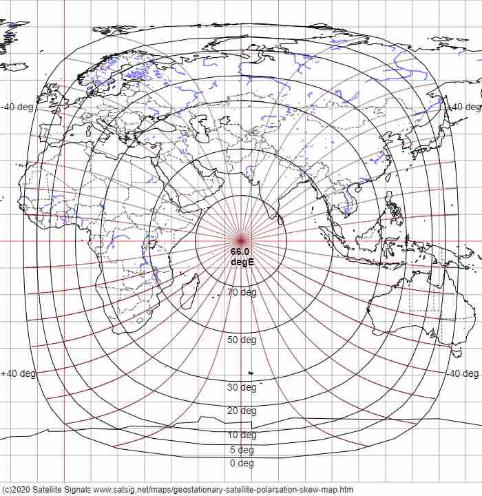
View from 66 deg east over the Indian Ocean region, showing connectivity between Europe, Japan, Australia and South Africa.
Some Eutelsat and Astra satellites, may not have their polarisations aligned with the equator. Errors of 3 deg and 7 deg are believed to apply. This minimised the polarisation adjustment required in the central region of the coverage area and reduced cross-polarisation interference during rain, since the bottom of falling rain drops tends to be horizontal.
Here is a global beam map image for the Es-hail-2 satellite at 25.9 deg east.
Circular polarisation
If you are using circular polarisation you do not need this page. Go to How to set up circular polarisation.
Use of this web page
This web page is not intended for use on mobile devices with small screen. The canvas picture image is 700 pixels wide. It may be copied to your PC using right mouse click and "Save image" as or "Copy Image".
The map data used is from the GSHHG v2.3.5 (Global Self-consistent, Hierarchical, High-resolution Geography Database), available from NOAA, a U.S. government agency.
Copyright notice: As of GSHHG 2.2.2, GSHHG is distributed under the GNU Lesser General Public License (LGPL) version 3 or later. Copies of the The GNU General Public License (GPL) and the GNU Lesser General Public License (LGPL) are distributed along with the sources. Permission to use, copy, modify, and distribute (with no more than a reasonable redistribution fee) this data and its documentation for any purpose is hereby granted, provided that the above copyright notice appear in all copies, that both that copyright notice and this permission notice appear in supporting documentation, and that the name of GSHHG not be used in advertising or publicity pertaining to distribution of the software without specific, written prior permission. The University of Hawaii (UH) and the National Oceanic and Atmospheric Administration (NOAA) make no representations about the suitability of this software for any purpose. It is provided "as is" without expressed or implied warranty. It is provided with no support and without obligation on the part of UH or NOAA, to assist in its use, correction, modification, or enhancement. The information must not be used for navigational purposes.
Page created 28 May 2020, last amended 1 June 2020, 12 May 2026. Eric Johnston
All pages on this satsig.net web site are Copyright Satellite Signals Limited © 2020 all rights reserved.