|
|
Antenna gain and beamwidth calculator Lat/long finder and dish pointing angles |
How satellite TV works.
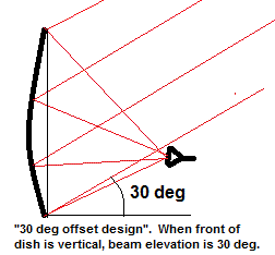
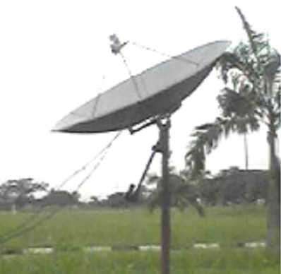
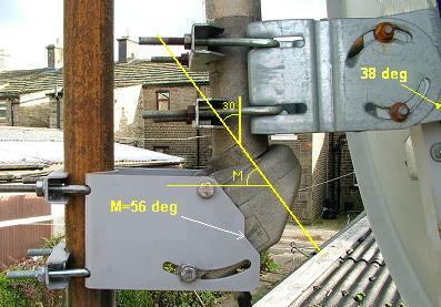
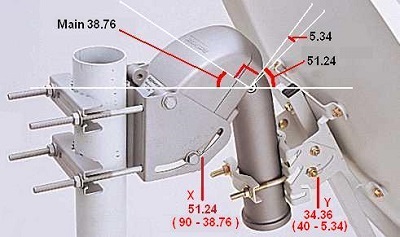
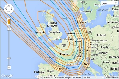
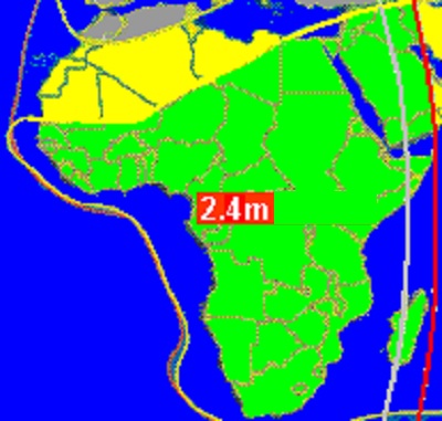
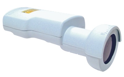
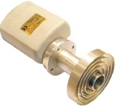
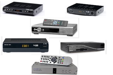
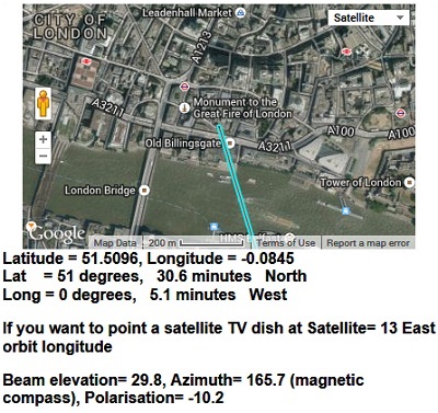
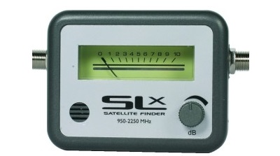
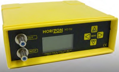
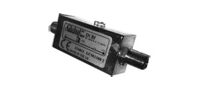
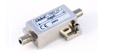
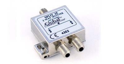
Antenna.There are two types of antenna used for satellite TV. The first is the offset design, as illustrate on the right. The second is a less common, classic dish shape called "circular axi-symmetric". The offset design has a single strong feed support arm at the bottom. The outline shape is not exactly circular. It is called offset because the beam elevation is typically about 30 deg when the front face of the dish is vertical. The advantage of this design is that the feed itself does not obstruct the beam. The axi-symmetric version has a truly circular outline and has the feed supported by three or four equal length struts, so that the feed is in the middle. The length of the feed support strut or struts is important. This makes sure that the LNB is correctly located at the focal point of the parabola. The focal length is the distance from the feed to the lower edge of the dish in the case of an offset design, and the distance from the feed to the centre of the dish in the case of an axi-symmetric design. Azimuth/elevation mount.At the rear of the reflector there is a mechanism with a scale to set the beam elevation (up/down). A beam elevation angle of 90 deg is straight up, with the satellite overhead. A beam angle of 15 deg is with the satellite down nearer the horizon. If the scale is missing, then an inclinometer is needed, plus information from the manufacturer about what is the dish offset angle. Azimuth angle (measured sideways from north=0 deg, east=90 deg, south=180 deg, west=270 deg) is set using the clamp that attaches the az/el adjuster to the vertical pole. Feed/LNB support clamp.At the end of the feed support arm is a circular clamp, to allow the LNB to be rotated and clamped at the correct polarisation tilt (also called skew angle). It is important that the diameter of the clamp (e.g 40mm) matches the cylindrical part of the type of LNB purchased. Dish size.Satellite TV reception dishes range from about 45cm up to around 3m diameter, according to the power expected from the particular satellite and beam at your location and the need to avoid interference from adjacent satellites operating on the same frequency. The on-axis gain of a dish increases with larger diameter, as does the discrimination against interference from adjacent satellites. Frequency bands.Several downlink frequency bands atre used: C band is 3.625- 4.2 GHz, Ku band 10.7-12.5 GHz and Ka band 17.7-20.2 GHz. C band is hardly affected by rain, Ku band is affected by rain, and Ka band more so. Broad area C band beams might typically cover all of Africa and need dishes of at least 1.8m diameter. Ku band is the most popular, with satellite beams covering smaller regions or individual country areas like North America, Europe or the UK. Dish sizes are under 1.2m. Ka band has recently been developed, providing primarily a satellite broadband service with dish sizes in the 70-98cm range. The internet bit rate available reduces during rainfall. Ka band spot beams may be used in the future to provide service to quite small areas. C band service may be affected by terrestrial interference from WiMAX and other local mast based systems such as 5G. Narrower band LNBs and filters are sometimes needed to stop unacceptable interference. The latest "Wide band LNB" may not be a good choice. Antenna surface.At the lower frequencies, like 4 GHz, fine mesh dishes have been successfully deployed. At Ku band perforated metal is satisfactory. At Ka band a solid metal is preferred. Whatever the material, distortion from a true parabola is to be avoided. At Ku band a surface accuracy better than 1.7mm (1/15th of wavelength) is recommended. Dishes with rims that are designed to be flat may be tested with the crossed strings test. Hygroscopic paints are available which will help repel water. Droplets are less a problem than a film of water. Offset designs and typical beam elevation angles often result in the the dish being near vertical. This helps minimise rain and snow problems. Motorised polar mountIf you want to frequently move the antenna to aim at different orbit positions, a motor driven polar mount is suggested. This allows the indoor set to box to control the antenna so that it points progressively to each satellite along the geostationary orbit line, on request. The motor type polar mount goes between the fixed vertical pole and the az/el bracket on the back of the dish. Two typical domestic motorised horizon-to-horizon (H-H) polar mounts are shown. Setting up a motorised polar mount may take some time. Some people have taken a week or more to do this. Low noise block down-converter (LNB).The LNB is located at the front of the dish on the feed arm. It comprises a feed plus low noise amplifier, mixer and local oscillator and an intermediate frequency amplifier, with output at 950-2150 MHz, called L band, into the cable. The feed, for an offset dish is typically a short conical horn covered with a plastic feed window. There may be a polarisation scale for setting the rotational angle in the clamp. The phase centre or focal point will be in the middle, about 5-7mm under the plastic feed window. For axi-symmetric dishes the feed is normally an open ended circular waveguide, surrounded by a flat plate with corrugated rings, called a scalar feed. The position of the scalar rings may be adjustable to suit the F/D ratio of the dish. e.g F/D=0.32 - 4.3. At Ku band the LNB used with this will have a C-120 waveguide flange. Find the focal length of a circular parabolic dish. The LNB is powered by a DC supply from the indoor set top box. The voltage is 13V or 19V and a superimposed 22kHz tone may be on or off. The voltage and tone options allow the indoor set top box to control the polarisation and segment of the frequency band. Read more about how an LNB works. Circular polarisation is used at C and Ka band. Linear polarisation is normal for Ku band. 75Ω Coax cable.A coaxial cable is used to connect the LNB to the indoor set top box. The type of cable used has an impedance of 75 ohms and uses F type connectors. It is desirable that it should be low loss up to 2150 MHz. Great care is needed making up the F connectors and sealing them against moisture as any moisture reaching the cable will cause rapid corrosion and deterioration. The liberal use of electronic grade silicone grease is recommended plus self amalgamating tape round the LNB connector. Cheap screw on F connectors are popular but are not waterproof. The type F connectors must match the cable diameter. The centre wire pin should protrude 1.5mm proud of the rim of the connector and should push in smoothly when connected, without 'pushing back' the cable. Remember that the outer braid must make good connection in order to carry the DC power to the LNB. Only work on the cable and connectors with the indoor set top powered off. Indoor set top box.There are very many types of receiver or set top box. Many older models are obsolete and are unable to receive the most modern DVB-S2/MPG digital modulation and coding. Indoor set top boxes come in two distinct forms. First is service specific. In this instance your equipment is intended for reception of a specific group of programs and typically just one orbit location, with a simple fixed dish. There is likely to be a slot for a conditional access card, which you pay for to decode the wanted programmes. The encoding system may require that you use the service providers set top box. The second type of receiver is general purpose and intended for the enthusiast who wants to watch programs from several orbit positions. Options may include control of a motor driven polar mount. Free-to-Air (FTA) programs are popularly receivable on a modern general purpose set-top box. Reception of encrypted programs may be limited to just one type of encryption, but you still need the correct, paid-for, conditional access card. Finding the satellite.Decide on your wanted satellite and note the orbit location using lyngsat.com Note the modulation type (e.g. 8PSK) and encryption type is applicable as this affects the type of set top box required. Then find your latitude and longitude and, after selecting your wanted satellite orbit position, read out and write down the beam elevation and azimuth angles and LNB polarisation angle (linear polarisation only). If you expand the scale you will see your house and a blue azimuth line showing the direction to the satellite. This will help you select a position for the antenna with a clear view of the sky. If you want to see several satellites work out and write down the pointing angles for each one. Put the LNB in its clamp and if the polarisation adjustment amount (also called skew) is positive, say +23 deg, then turn the LNB by an amount of 23 deg clockwise as seen from the point of view of you standing behind the dish, facing towards the satellite in the sky. Ignore any +/- on the scale if it goes the wrong way. Make sure the pole behind the antenna is upright. Set the elevation scale to slightly more (say +1 deg) than the required beam elevation angle and tighten the clamp to the pole to hold it steady but no so tight that you cannot swing the dish sideways. Aim the dish at the approximate magnetic compass angle (blue line). Swing the dish boldly sideways to find the satellite. Peak up very carefully to the maximum signal in both azimuth and elevation. For some satellites, Eutelsat and Astra, it is also necessary to further rotate the LNB polarisation to minimise cross-pol interference. Satellite meters and spectrum analysers.If, from the antenna, you can see the TV screen connected to the set top box then you may use that as a guide to pointing, peaking up and identifying a satellite. Alternatively, and preferably you may use some kind of satellite signal meter close to the antenna. The cheapest option is broadband power meter which simply measures the total signal power in the cable. the meters has two connections, one goes to the LNB, the other connects to the set top box which provided the power. This cheap solution works very well in allowing you to see when you go past a satellite, see the needle move, and to then peak up. You need to then use the set top box to identify the satellite. Hopefully it is the wanted one. If not, move along the orbit arc till you get to the wanted satellite. A range of satellite meters are illustrated here: Sadoun Signal-Meters The more expensive meters such as "Horizon" model, if they are programmed correctly and you are using the expected type of LNB and polarisation, indicate the name of the satellite found. Spectrum analyser type meters show multiple carriers and allow accurate cross-polarisation adjustment and interference assessment. Surge protector.It is a good idea to ground the antenna structure and to ground the outer conductor of the coax as it enters the building to minimise fire and personnel hazards in the event of lightning strike. This may be a legal requirement in some countries. Surge protectors for the centre wire of the coax do exist but I've only ever used such things once. They help protect the indoor equipment. Search Google for "coax lighting arrestor" or "coax surge arrestor" DC Block or Power Inserter.This is needed if your indoor set top box does not provide a DC power supply the LNB. It may be helpful to have a multi-voltage PSU, +13 and +19 volts. A DC block is essential to protect spectrum analysers which will not tolerate any DC input. L band line amplifiers - Preamps.L band slope amps are useful for very long cables. e.g. put one slope amp midway along a 60m cable run. The gain of the in line amplifier increases at the higher frequencies to compensate for the higher cable attenuation. The active amplifier component is powered by the DC supply which mostly continues through to the LNB. Splitters.An L band splitter is useful indoors to provide for multiple receivers or for receivers and test equipment such as a spectrum analyser. Make sure at least one path though the splitter has "DC PASS" if you want to power the LNB from a set top box. Be careful never to allow DC to get to the input of a spectrum analyser that has no DC protection. 4 way and 8 way splitters are available; also versions with active amplifiers to compensate for the splitter loss. |
|

|
This page is not a paid-for advert for Sadoun, Horizon or Global. Their products are simply featured to illustrate examples of what may be purchased from many manufacturers. ► Page created 8 October 2014, amended 10 June 2021, 7 May 2026, 22 July 2026. All pages on this satsig.net web site are Copyright SSL 2014 all rights reserved. |