Overcoming the “Zenith Pass” Crisis: A Guide to Satellite Tracking Pedestal Selection
(Read 31 times)
Antesky Vicky
Senior Member
★★★ Offline
Posts: 75
Yesterday at 2:24am
For ground station engineers and satellite operators, “Zenith Pass” (when a satellite flies directly overhead) is the ultimate stress test.
In low Earth orbit (LEO) tracking, everyone dreads the moment the satellite approaches a 90° elevation angle. On paper, it is the shortest path with the strongest signal. In reality, for many traditional ground terminals, it is a “dead zone” where tracking fails, motors overheat, and critical data is lost.
Why is tracking directly overhead so difficult? And how do you choose the right pedestal architecture to eliminate this blind spot? Let’s dive deep into the 4 mainstream tracking solutions in the Satcom industry today.
The Root of the Problem: Gimbal Lock and the Mathematical Singularity Imagine tracking a ball passing directly over your head. If you use a traditional Azimuth-Elevation (Az-El) 2-axis pedestal, your Azimuth axis rotates horizontally, and your Elevation axis tilts vertically.
When the satellite reaches the exact 90° zenith point, your antenna’s boresight aligns perfectly with the vertical Azimuth axis. At this precise mathematical “singularity” (or Gimbal Lock), the definition of Azimuth angle becomes meaningless.
If the satellite moves even a millimeter past the zenith, the tracking algorithm screams for the Azimuth motor to instantly rotate 180 degrees to keep up. Because physical motors cannot achieve infinite angular acceleration (ω→∞ ), the antenna lags behind, causing the notorious “Zenith Blind Spot” or “Keyhole Effect.”
To solve this, the industry has developed different mechanical approaches. Let’s look at how they perform in the real world.
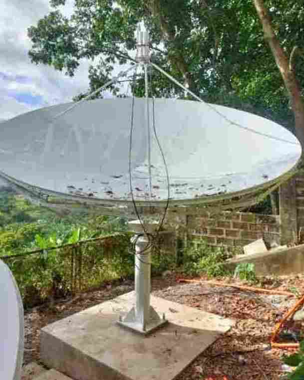
4 Mainstream Satellite Tracking Pedestal Solutions: A Deep Dive Solution 1: Traditional Az-El (Azimuth-Elevation) 2-Axis Satellite Tracking Pedestal The most common and classic architecture. The azimuth axis rotates 360° or limited sectors horizontally, and the elevation axis moves 0-90° vertically.
The Verdict: Great for Geostationary (GEO) or Medium Earth Orbit (MEO) tracking where maximum elevation rarely exceeds 75°. It is simple and cost-effective but guaranteed to drop connection during a LEO zenith pass.
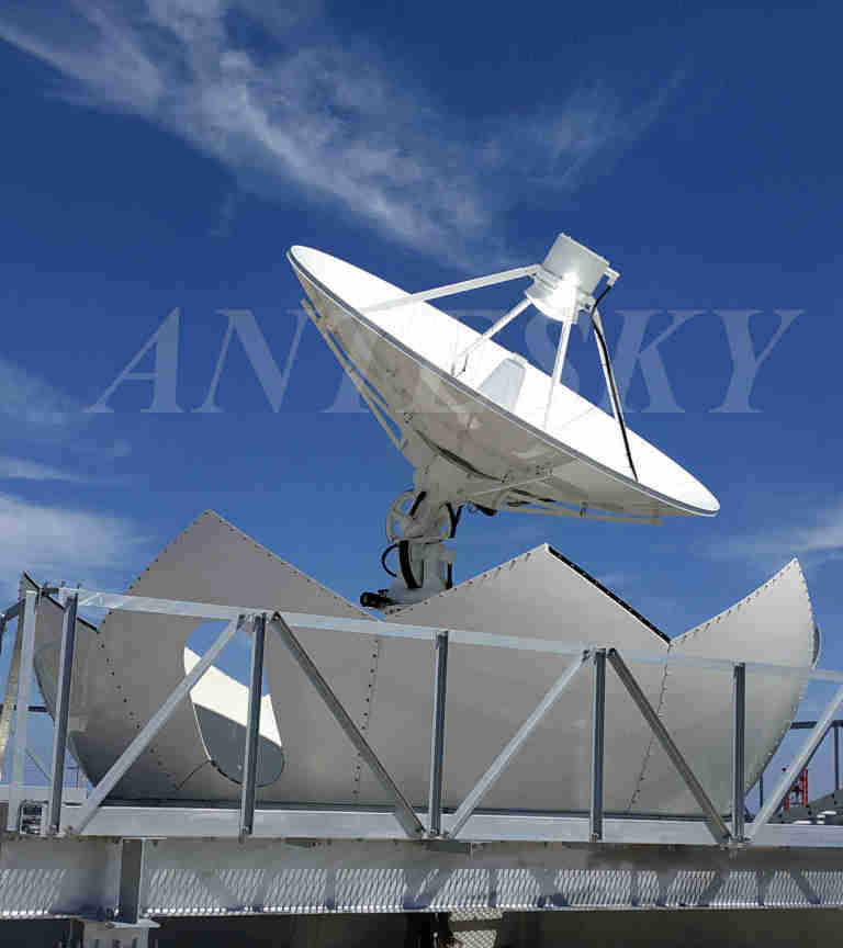
Solution 2: X-Y 2-Axis Satellite Tracking Pedestal Instead of having a vertical azimuth axis, this structure places two rotating axes horizontally, orthogonal to each other (X-axis and Y-axis), resembling a cradle or a gantry.
The Verdict: Excellent for tracking satellites directly overhead. When a satellite passes the zenith, the X-Y pedestal moves smoothly like a pendulum without any sudden speed spikes. However, its blind spot is transferred to the horizon (low elevation angles). Furthermore, due to the overhanging mechanical structure, it requires a massive footprint and lacks structural rigidity under heavy winds, making it highly unsuitable for mobile setups.
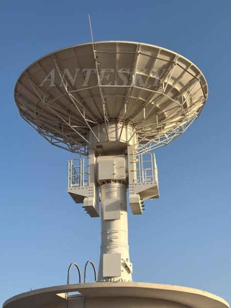
Solution 3: Az-El-Tilt 3-Axis Satellite Tracking Pedestal By adding a third, orthogonal Tilt axis to the traditional Az-El structure, this architecture solves the zenith problem through geometry.
The Power of the 7° Tilt: While mobile systems require wide-range tilts, our fixed LEO ground stations utilize a highly optimized “Small-Tilt” 7-degree design. When a LEO satellite approaches the absolute 90° zenith, the Tilt axis slightly offsets the antenna pedestal by just 7°. This precise micro-leaning action is mathematically enough to push the singularity point completely out of the tracking path. The Azimuth axis no longer needs to violently spin 180°, allowing for ultra-smooth tracking. Result: 100% seamless, uninterrupted data tracking across the entire sky with maximum mechanical stability.
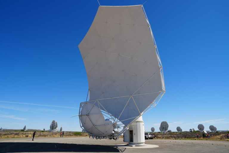
Solution 4: Heavy Hydraulic Servo Systems Replacing electric motors with high-pressure hydraulic cylinders and servo valves to drive massive structures via pure fluid power.
The Verdict: “Brute force” at its finest. It offers extreme mechanical stiffness and massive torque, capable of moving strategic 30-meter to 70-meter deep space tracking dishes weighing tens of tons. However, due to its massive footprint, maintenance nightmares (oil leaks), and environmental sensitivity, it is unfit for commercial, vehicular, or marine deployment.
Dimension Az-El 2-Axis X-Y 2-Axis Az-El-Tilt 3-Axis Hydraulic Servo Payload Capacity Moderate Moderate High Extreme Zenith Performance Poor (Blind spot) Excellent Perfect (No blind spot) Good (via brute force) Horizon Performance Excellent Poor (Keyhole at horizon) Excellent Excellent Complexity & Footprint Low / Compact High / Bulky Balanced / Compact Extreme / Massive Ideal Environment Static GEO Ground Stations Fixed LEO Remote Stations Fixed LEO Remote Stations Deep Space / Strategic Radar
Finding Your Perfect Tracking Solution We understand that engineering is about choosing the right tool for the right battlefield. That is why we offer a comprehensive lineup of electric motor-driven solutions—ranging from cost-effective Az-El 2-axis pedestal and fixed X-Y pedestal, to 3-axis LEO tracking pedestal.
Ready to eliminate your zenith blind spot? Contact our engineering team today to find the perfect pedestal for your payload.
Please note that I have adjusted the images sizes in the above to reduce the bytes from a total of 647k bytes to 99k bytes so as to stop pages in this forum from being downgraded due to excessive average load times on slow 4G mobile phones. During April over one thousand pages in this forum were downgraded in Google Search, which got me in a bit of a panic. The average download time (of forum pages) exceeded 2.5 seconds. Now the good news. I got the average down and it is now under 2.5 seconds and all those 1151 pages in the forum are now released as OK in Google Search. Hooray!
Just tested. Now 2.1 seconds download compared with 5.14 sec before.