|
|

| SatSig Topics Index › HughesNet and Hughes HX VSATs › HX50 in Afghanistan pointing issues (HX W6) |
SatSig topic: HX50 in Afghanistan pointing issues (HX W6)(Read 17019 times) |
|
Sep 14th, 2009 at 6:30am
Lat/Long: 34.4N, 70.3E EL: 24.8 AZ: 242 POL: 48.2 LNB receive type: unknown Bentley Walker sent me this: Symbol Rate: 5000000 LNB 22KHz Switch: Off DVB Mode: DVB S2 ACM Frequency Band: KU/QPSK Receive Pol: Vertical Transmit Pol: Horizontal VSAT return: inbound Transmit Radio: 2 watt We have set the elevation (with an inclinometer), done sweeps on the azimuth and rotated THE ENTIRE DISH to the correct polarization. Additionally, we've set the LNB to vertical polarization (to the side) while keeping the 5-0-5 and the single notch away from the feed arm. THE PROBLEM: Last night, i pointed the dish to a signal of 27. After reading some of the posts on the forum, i changed the LNB receive type to Pure and restarted the modem. After it restarted, and without touching the dish, the signal dropped to 15. I changed it back, restarted and the signal remained 15. Now i'm completely lost and don't know what to do next. Any suggestions? |
|
Sep 14th, 2009 at 1:14pm
This is BW support. If you are having issues may be it will be better if we refer you to someone locally that can set the dish up for you , do you wnat me to pursue this for you ? |
|
Sep 14th, 2009 at 3:12pm
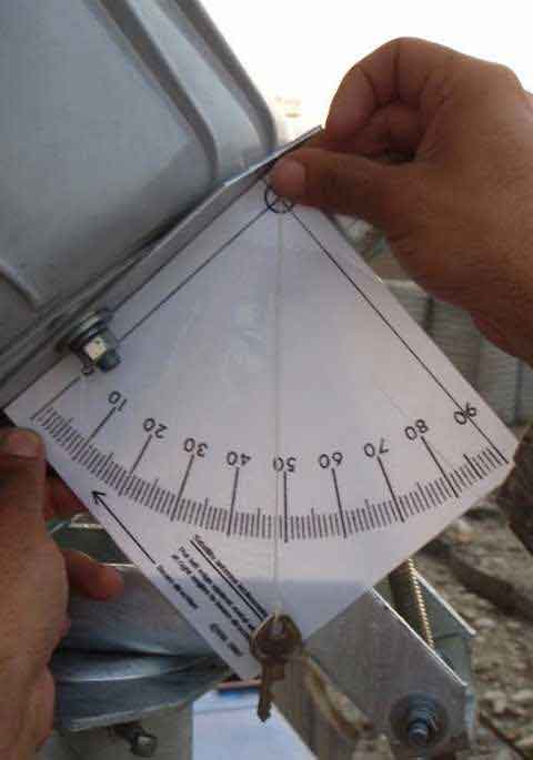 Anyone without an inclinometer can make one like that above by printing out this page Inclinometer Tell us the make and model number of the LNB you have. Tell us the receive frequency you have configured in the modem. With the LNB set to "Pure" try swinging the dish again to find the satellite. Changing the LNB settings will make some LNBs (INVACOM SPV 30 or 31) switch between different local oscillator frequencies. The satellite downlink frequency minus the LNB local oscillator frequency = the modem frequency. For example: Satellite down = 11.3805 GHz LNB LO frequ = 10.000 GHz Modem tuning = 1.3805 GHz = 1380.5 MHz (actually input to the HX modem as 13805, in units of 100kHz ) Example LNBs: NJR2784 LO = 10 GHz NJR2744 LO = 10.75 GHz NJR2754 LO = 11.3 GHz Invacom SPV-50 LO= 10 GHz Invacom SPV-60 LO= 10.75 GHz Invacom SPV-70 LO= 11.3 GHz Invacom SPV-30 LO=9.75 or 10.6 GHz (switched 13/19V) Invacom SPV-31 LO=10 or 11.3 GHz (switched 13/19V) Read more: NJR LNBs Invacom LNBs If you have anomalies with the receive signal then it may be that the LNB cable connections need attention. Always power off at the mains wall switch before interfering with the coax cables or the low voltage multi-way connector between the power supply module and the modem. Regarding the coax cables and the F connectors. The centre wire pin should stick out 1.5mm proud of the rim. The braid sheath should make good contact with the plug outer. There must be no fragments of braid copper foil or wire shorting out the cable. When screwing in the centre pin should slide smoothly into the hole and not push back the cable end within the plug. Use firm finger tightness only, even if it hurts your fingers a bit but do make sure it is properly screwed in. Don't use a wrench and damage the LNB or modem internally. Do not get the coax cables crossed over. You may wish to do all testing and adjustment with just the receive cable connectced until you have the best signal. Once you have found the satellite the signal level will go above 30 up to near 100, and you then need to spend at least 30 minutes peaking up. Peaking up is more difficult than finding the satellite. Best regards, Eric. |
|
Sep 14th, 2009 at 3:53pm
Satellite frequency reads 13805. I've checked the cable, everything seems fine. I'll try again tonight with the inclinometer that i've just printed out. I have another question regarding the polarity. My Rx polarization is vertical and my Tx is horizontal. The LNB is turned 90 degrees while keeping the 505 and single line opposite of the feed arm. The instructions indicate the BUC is also rotated 90 degrees for horizontal polarity. Are both supposed to move, or only the LNB? I'll try and snap some pictures of the setup tonight and email them. |
|
Sep 14th, 2009 at 5:18pm
We don't normally use the Invacom LNB for Afghan, it is usually a High Band NJRC for Sesat and a Low Band for W6, can you email in the morning the type of LNB and which satellite you are aiming for. Are these systems you bought directly from Bentley Walker or where did you buy them from ? We will help you to get on line so please email me soon as you can anthony@bentleywalker.com Best Regards |
|
Sep 14th, 2009 at 5:49pm
For vertical name receive polarisation: Always assemble the feed so that the 505 is directly away from the feed arm. The LNB side arm should be at the side. This gives true vertical polarisation when the feed support arm is at the bottom, in the middle. Adjust the polarisation (as calculated for the site location). In this case, the entire dish may be rotated +48 deg clockwise, as seen from the rear of the antenna with you facing towards the satellite in the sky. Note: If you have assembled the feed for nominal horizontal polarisation. i.e. the 505 directly away from feed support arm and LNB arm directly away, upwards, from feed support arm. Then, with the feed arm at the bottom you have true horizontal polarisation. If you turn the entire dish 90 deg, so the feed arm is at one side then you are true vertical polarisation. Then apply the adjustment angle. It will work perfectly, even if it looks bizarre. Frequency I have just spoken with BW. The downlink frequency for W6 Afghanistan is 11.3805 GHz. The appropriate LNB has a local oscillator frequency of 10 GHz. The resulting coax cable frequency into the HX modem is 1.3805 GHz. The HX tuning frequency entered on the config set up screen is 13805 (in units of 100kHz.) LNB type Your LNB P/N 1500287-0001 is a Hughes part number. LNB P/N 1500287-0001 10.95 - 11.45 LO=10 GHz LNB P/N 1500287-0002 11.7-12.2 GHz LO=10.75 (my guess) LNB P/N 1500287-0003 12.25 - 12.75 LO=11.3 (assumed) HX Signal readings The scale is in two parts 0 - 29 and 30 - 100. If you get a reading maxed out at 29 and it won't go any higher you are pointed at some powerful satellite but there is something wrong: Wrong polarisation, wrong type LNB, wrong tuning, wrong symbol rate, wrong satellite. Once the wanted carrier is recognised the reading will immediately go up into range 30 - 100. Peak up to the absolute peak value or, more easily, peak up by mechanically halfing the distance between two exactly equal but slightly degraded levels either side of the beam. Best regards, Eric. |
|
Sep 14th, 2009 at 6:34pm
A few lessons learned: -Use the printout inclinometer. I originally used an electronic one that's calibration must have been off. Sometimes the simplest method is the best -With the LNB and feed horn staying in the same position (vertical pol, 505 and single tick on top), I rotated the BUC 90 degrees anticlockwise as looking at the dish from the LNB. I have seen a lot of posts involving changing the nominal polarization of the LNB, but very few involving the polarization of the BUC. I guess this is what the manual was referring to as "horizontal polarization". Straight out of the box, one could disconnect the feed horn, rotate the entire LNB/BUC setup 90 degrees and then re-attach the feed horn so the 505 and single tick were still opposite the feed arm. I don't know if this is proper, but it's what worked for me. We'll see what happens after i try to commission the modem. Again, thanks to everyone who helped...I really appreciate it. This forum is a HUGE asset to anyone trying to install a dish. |
|
Sep 14th, 2009 at 11:04pm
So, it would appear that LNB Hughes P/N 1500287-0001 is a NJR 2784HH and has a 10 GHz local oscillator. You have the receive side working well so your polarisation is at least in the right general area. The polarisation is best set by calculation and using the giant scale. During commissioning BW can test your polarisation isolation and talk you into the deep null if necessary. The correct deep polarisation null is only about 1 deg wide. Big variations in polarisation angle (+/- 10 deg) will make little difference to the wanted co-pol signal and it is not practical to use the wanted carrier quality to adjust the polarisation. Regarding the transmit BUC. The 12 hole flange at the end of the tapered spacer tube, where is the single and double tick marks is where the polarisation may be set to nominal horizontal name (LNB upwards) or vertical name (LNB at side). Picture below received this morning and inserted here: 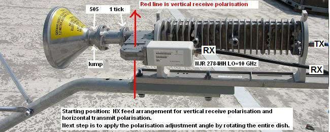 Best regards, Eric. |
|
Feb 24th, 2010 at 4:17am
|
|
Feb 24th, 2010 at 10:49am
First set the starting position: Rotate the polarisation scale on the back so the entire dish has the feed arm in the middle at the bottom. Set the LNB upwards for horizontal receive polarisation. Set the LNB at the side (either side will do) for vertical receive polarisation. Make sure the 505 is directly away from the feed arm and fat lump towards the feed arm. The 12 hole flange may need to be undone and reattached. Step 2. Apply the polarisation adjustment angle. Stand behind the dish and turn the entire dish clockwise, while facing towards the satellite in the sky for + angles. Note that if you keep turning the dish all the way round the polarisation twice goes through vertical and horizontal. It looks stange when the feed arm is up high but it will in fact work just fine. Any of the 90 deg quadrant positions of the LNB may be regarded as starting positions. Don't choose a final position where the dish becomes a bird-bath ! The direction of polarisation is defined by the quarter wave dipole antenna pin inside the LNB waveguide. If the broad faces of the waveguide face sideways that is horizontal polarisation, like so:   Both LNB waveguide images show horizontal polarisation. Best regards, Eric. |
|
Sep 30th, 2010 at 1:40pm
|
|
Sep 30th, 2010 at 2:43pm
Transmit and receive coax cables. The wire on the right of the picture above is the transmit cable. The transmit cable is connected to the 'IFL' socket on the back of the long grey finned transmit BUC module. Next to that socket it is an unused test socket, normally blocked off with a plastic cover. The receiver is the small LNB module (approx 1.5 inches square and 4 inches long) nearer to the feed. I've modified the image above to distinguish between the TX (transmit) and RX (receive) cables. Polarisation In the case of a discrete simple single frequency LNB (e.g. NJR2874), as shown in the image above, the polarisation is defined by its rectangular input waveguide. The direction of receive polarisation is at right angles to the broad faces, i.e in the direction that the broad faces are facing. Both of these waveguide images below are vertical polarisation. It makes no difference if the dipole pin points up or down, either way is vertical:   Like the image above. The pin (the quarter wave dipole antenna pin, is vertical = vertical polarisation). Note the Like the image above. The pin (the quarter wave dipole antenna pin, is vertical = vertical polarisation). Note the RED receive polarisation line.In the case of the white universal LNB/OMT PN 1501882-0002 the receive coax cable comes out of the end of the LNB and the cable is the same as the direction of receive polarisation. There is no rectangular input waveguide to the Universal LNB is not visible and the LNB is integrated with the OMT. The transmit poarisation is obvious however(see BUC waveguide), so receive is the opposite. 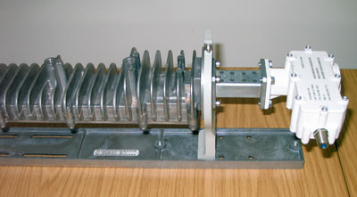 As shown, the transmit polarisation, from the BUC on the left, is vertical. Receive polarisation is Horizontal. Best regards, Eric. |
|
Sep 30th, 2010 at 5:15pm
I say that because - other than the Osiris TG model that you show in those photos - most Hughes TRIAs bolt either directly to the feedarm, or to their cradle and then to the feedarm. That means the bolt holes will by design be either facing down or up. In the non-TG configurations, the default TX polarization must be horizontal. To go vertical in other than the TG cradle requires a vertical shim. Consider the photo of my "pure" Osiris: 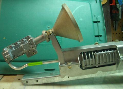 and note the bolt positions. What you're looking at is the H/H configuration. Along with Chinon, Isis, Anubis TRIAs, it can't rotate in its cradle (like the Osiris-TG), meaning that they're of a fixed TX polarization And in my part of that world, that fixed polarization defaults to horizontal. Switching TX polarization requires the insertion of a vertical shim. and note the bolt positions. What you're looking at is the H/H configuration. Along with Chinon, Isis, Anubis TRIAs, it can't rotate in its cradle (like the Osiris-TG), meaning that they're of a fixed TX polarization And in my part of that world, that fixed polarization defaults to horizontal. Switching TX polarization requires the insertion of a vertical shim.//greg// |
|
Sep 30th, 2010 at 6:06pm
* The broad faces of the transmit waveguide are horizontal and face upward and downwards, so transmit polarisation is vertical as it leaves the BUC Unless there is a 90 twist inside the filter/OMT assembly.... Here is another picture. 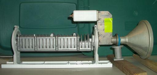 Do you agree that this is picture shows Horizontal receive and Vertical transmit ? Best regards, Eric. |
|
Sep 30th, 2010 at 7:56pm
Not sure I understand. In your 'greenish' image there is a silver coloured waveguide from the BUC to the filter/OMT assembly. This silver tube appears to have a rectangular or elliptical cross section. The broad faces of the wavguide are up and down, so transmit is vertical polarisation as it leaves the BUC. Unless there is a 90 twist inside the filter/OMT assembly.... No sir, that TG rig is actually my hot spare. It's configured H/H in that photo, just in case something goes wrong with the "pure" OSIRIS that I'm currently using on a H/H access. You've interpreted the photo incorrectly. The broad faces of that silver w/g section are in fact horizontal. Externally, it's 14.6mm wide, 8.7mm high.Here is another picture. https://www.satsig.net/images/greg/osiris-tg2.jpg Do you agree that this is picture shows Horizontal receive and Vertical transmit ? Best regards, Eric. The LNB is electrically switched; 18v for H, 13v for V. But if I had to move to a transponder where a vertical uplink was required, I'd have to physically install a 90 degree hardware shim. HughesNet consumer grade uplinks in North America are Horizontal by default. Business/enterprise grade on the other hand, can be either H or V (depending upon GOS). But even then - with the exception of TG type TRIAs - a 90 degree shim must be installed for Vertical uplinks. Now. That said, what do you think the chances are that Hughes deploys different transmitters to your part of the world? They're awful hard to read once installed, but - if you wish - we can compare Hughes part numbers. Because a situation where the two of us were offering conflicting info to enquiring members, simply wouldn't do. //greg// |
|
Sep 30th, 2010 at 11:01pm
Where I said "The broad faces of the wavguide are up and down, so transmit is vertical polarisation as it leaves the BUC." I have changed this to read: * "The broad faces of the transmit waveguide are horizontal and face upward and downwards, so transmit polarisation is vertical as it leaves the BUC." I don't know if there is a polarisation twist, or option for a shim twist ?, inside the filter/OMT assembly. The BUC itself has an output waveguide like so: when the finned face of the BUC is upwards. so the transmit polarisation is vertical at that point. Best regards, Eric. |
|
Email me:eric@satsig.net |