|
|

| SatSig Topics Index › iDirect Forum: hubs and terminals › Frequency hopping mode in iDirect network |
SatSig topic: Frequency hopping mode in iDirect network(Read 14210 times) |
|
Dec 14th, 2010 at 6:22pm
I'm a newbie in this forum. Ok, i have a question: I'm a supervisor on a hub iDIRECT HD DVB-S2 in the south pacific. The technicians tell me that frequency hopping allows the timeslot to jump from one carrier to another inside the same inroute. But in their guide, iDIRECT certifies that frequency hopping let the hub load-balances across all inroutes. I think technicians are wrong. What do you think of it? And if I'm right, are there any particuliar specifications in the inrout group? Please forgive my bad English |
|
Dec 15th, 2010 at 3:37pm
Furthermore, Frequency hopping refers to FDMA type of satellite access where you are given a frequency range. When your carrier pops out, it will find a vacant spectrum on the allocated range within the transponder.This simply means spectrum sharing. In lastly, your technician study went wrong  Regards, Jawad Malik Email: jawadg@hotmail.com |
|
Dec 15th, 2010 at 7:17pm
|
|
Dec 15th, 2010 at 8:58pm
Best regards, Eric. ( terminology in this posting adjusted to match iDirect documentation ) |
|
Dec 16th, 2010 at 11:50pm
"Frequency Hopping mode provides true run-time load balancing across all the inroutes within an inroute group. In Frequency Hopping mode, remotes will dynamically load-balance across all inroutes in the group based on inroute demand. The Protocol Processor analyzes upstream demand from all remotes and automatically allocates timeplan slot assignments to achieve an equal balance of remote demand across all the inroutes. Remotes will hop from one inroute to another either on a frame boundary or within the same frame depending on the nature of the demand." |
|
Dec 20th, 2010 at 3:27pm
You can have multiple carriers in an iDirect network (multiple Rx links) The remotes can be configured to Transmit on these carriers in a couple of ways. 1. they can be locked to a single carrier, (carrier grooming) this is inefficient as you may have all remotes on one inroute carrier trying to burst, while another inroute carrier may have no remotes trying to transmit. therefor leading to an unbalanced load across the Rx channels, wasted bandwidth etc. 2. Frequency hoping. Based on demand (from Remote) the protocol processor looks at the demand for bandwidth from all remotes in the network, it then makes the bandwidth allocation calculations (priority, cost etc) this bandwidth is then allocated to the remotes across the available inroute carriers. the carriers have to have the same characteristics - size, # of slots etc. The remote is able to use multiple carriers to transmit in a frame, it does not have to stay on a single carrier, if a carrier is used by another remote of higher priority, then the system will move other remotes to available carriers. FH mode basically allows the PP to ensure the bandwidth available across the whole inroute of the network (multiple carriers) is available to all remotes. Couple of points. 1. if you have FH in your system and you have poorly commissioned remotes (CRC errors etc) then the errors will bounce across all inroute carriers, possibly affecting everyone. (this actually catches people as they think all carriers have an issue, when in fact it can be a single remote) 2. the system will not allow you to share the inroute carriers using FH is you do not have the characteristics set the same. (obviosly not frequency, but the others such as carrier size, frame length etc) 3. FH is absolutely the way to set up the system for best/most efficient performance, FH ensures full availability of your bandwidth to all remotes. 4. FH does not mean a remote can transmit on multiple carriers at the same time, it can only transmit on one of the carriers, then switch to the other, it is not a way to increase the overall bandwidth available to a remote, if you have three carriers of 1Mbps on the inroute and a single remote, the total inroute capacity you have for that remote is still 1Mbps not the combined total. your technicians are almost right, FH is not letting timeslots jump from one carrier to another, it allows the remote to transmit on one timeslot in one carrier, then transmit on another timeslot on another carrier in the same inroute group. this can happen in the same frame, the limit I think is the remote must have a 2 timeslot gap between transmitting on one carrier and another. in a frame with 70 slots, 125ms frame length, this means the remote will switch in around 3.5ms from one carrier to another. when the idirect platform is in normal operation, the timeslots are feathered, (spread out) to avoid jitter etc, so the jump from one carrier to the other is seamless as far as the user is concerned. By the way, I am a big fan of the FH mode of operation, it has been in use for a long time now and is a huge gain in efficiency. |
|
Dec 20th, 2010 at 8:41pm
I think i'll have more questions for you in the next future. |
|
Dec 21st, 2010 at 11:25am
|
|
Dec 22nd, 2010 at 8:30pm
Ask any questions, most of the guys on here are just genuinely interested in passing on knowledge and improving the Sat industry standards. |
|
Jan 24th, 2011 at 7:18am
please elaborate, thanks. |
|
Jan 25th, 2011 at 8:25am
Is it possible for a Single Outbound and various Inbound Channels to work in a Single Inroute? And, Does the FH apply in Both Inbound and Outbound? Have a good day. |
|
Jan 25th, 2011 at 10:56am
Well, Can anybody elaborate more about the Inbounds and the Outbounds? I'll give it a try, even though I know nothing specific about iDirect. Inbound traffic comes from remore sites to the hub. Outbound traffic go from the hub to the remote sites. A network will typically have one large outlink carrier and many smaller inbound carriers. All sites share in the downloading capacity of the large outbound carrier from the hub. e.g. 1 Mbit/s download capacity shared amongst 50 sites. If you have two return link carriers, each 256kbit/s then you might permanently allocate 25 sites to one return link and 25 sites to the other return link. Alternatively you might allow Frequency Hopping so all 50 sites may use either of your two return link frequencies, as chosen according to the instantaneous traffic load. Quote: I checked about the Frequency Hopping from one Inbound (Carrier to the other in my n/w). If you saw inbound traffic from a site hop from one inroute carrier to the other then your Frequency Hopping is obviously working. Quote: Is it possible for a Single Outbound and various Inbound Channels to work in a Single Inroute? This does not make sense to me. The outbound traffic is in the outroute carrier only. The inbound traffic is only on the inroute carriers and may be scattered across multiple inroute carriers by Frequency Hopping and according to traffic load on each inroute carrier. If you have only one inroute carrier then you can leave Frequency Hopping switched off as it can't do anything anyway. If you have more than one inroute carrier then Frequency Hopping helps by spreading the traffic load. Quote: And, Does the FH apply in Both Inbound and Outbound? Frequency Hopping is only applied to inbound traffic and in networks with multiple inroute carriers, each inbound carrier being on different frequency. On the single outlink carrier the traffic for all sites is queued up and sent as sequential packets in the data stream. Each site receives ALL of the outlink traffic but each site only extracts packets specifically intended for it and then forwards these packets to the local customer's ethernet cable. Best regards, Eric. |
|
Jan 31st, 2011 at 3:08pm
I have another question for you guys, what is the root cause of the alarm "Hub modem traffic CRC above high limit"? please elaborate, thanks. Eric answered the FH question pretty fully so I'll take this one The Hub Modem CRC error is exactly what it says.....the Hub Modem is the line card. So the Line card is receiving CRC errors over the limits set. these can be viewed on the line card stats as either Acq CRC errors or Traffic CRC errors. Axq (acquisition) errors can be caused by a remote attempting to join the network and the burst being offset too much in timing, or frequency or power. Traffic CRC errors are more of an issue, once a remote acquires, the hub typically balances the power, frequency and timing so the Acq CRC errors go away. the traffic CRC errors however are more permanent, you can use a process called CRC correlation, explained in the iMonitor user guide, to identify which remote or remotes are causing you CRC errors on your line card. once you have identified the remote, you need to start looking at what the issue is, do you have a remote transmitting in saturation? is there an issue with the BUC? is it one remote, or all remotes? is the issue with your hub Rx chain? A common issue with the remote that is causing CRC errors at the line card is the cabling. so once you have identified the remote responsible get the cabling checked out. Please read the whole CRC correlation guide before attempting it, you have to add custom key to the system and work in the PP and line card using SSH, if you are not comfortable with this, don't mess with it. It could also be false burst detection causing the line card to report CRC errors. You can tell the false bursts CRC errors pretty easily with a dump of traffic at the telnet prompt of the line card. the command: dumpb -c 50 will dump the next 50 CRC errors reported. you'll notice a CRC=0 , that is a CRC error. check out the SNR and the data section of that line....is the SNR 0 or very close to 0? and does the data (string of letters at the end of the line) look very different from the data when you do a: dumpb 50 check the CRC=1 line, clear off CRC errors. to sum up: CRC errors due to Acquisition are common when bring remotes online and typically go away as the remote settles into the network. CRC traffic errors need to be hunted down and eradicated! they are not just interruptions in the traffic of the remote causing them, but will cause loss of packets for other remotes in the network. follow the steps to identify the remotes causing the errors, then work on those remotes to bring them in line. |
|
Feb 2nd, 2011 at 10:27am
I would add that it you put a spectrum analyser on the return link frequency in max hold you can watch the spectrum envelope build up. Watch for any bad burst that fills up the gaps to the adjacent return links. Also look for interfering carriers, a sweeping CW etc. It makes sense for a hub to have a spectrum analyser always on, watching the frequency range of interest (with max hold off). Look on the opposite polarisation also - it is not unknown for bad cross pol TDMA bursts to trigger a receiver. Test with the spectrum analyser in zero span, single sweep mode. Keep pressing single sweep till you detect the bad burst. It may be too low level, too high level, chirpy in level, overlapping etc. Try moving sites to other return links to isolate which site is the problem. If you have a spare return link put a site there to test it in isolation. Best regards, Eric. |
|
Jun 17th, 2011 at 1:43pm
|
|
Jul 12th, 2011 at 8:24am
Test with the spectrum analyser in zero span, single sweep mode. Keep pressing single sweep till you detect the bad burst. It may be too low level, too high level, chirpy in level, overlapping etc. What is the SpecAn settings for RBW,VBW, Sweep time, Detector mode, etc? Many thanks.. |
|
Jul 12th, 2011 at 9:21am
To observe one TDMA carrier in zero span set the RBW the same as the carrier bandwidth if possible, else less. VBW = Video bandwidth. This is the bandwidth of a low pass filter (starting at DC) that comes after the detector. If the analyser frequency sweep is stopped (i.e. in zero span) then a steady signal will produce a DC output. If the signal is a 20mS long TDMA burst the signal level should rise up, go along and then down, displaying a rectangle. For such display to look right you need a video bandwith of at least 1 kHz, so that the the leading and trailing edges are shown clearly. If you set VBW to too slow, like 10 Hz, the start and end will appear falsely smoothed and rounded. Sweep time = This is the time it takes for the spot to move across the screen. Try 1 sec sweep time in single sweep mode and keep clicking till you see something interesting, such a steam of bursts from a particular site. You can use continuous sweep and peak hold during very light traffic periods and also for detecting intermittent interference into your return links. If you are a hub operator I suggest you have a spectrum analyser looking at all your return links. Detector mode = You need to read up about this for the particular analyser as the method varies. The detector may comprise a peak reading voltmeter. How the output is displayed and its interpretation depends on the nature of the signal. Normally the output display will be power in units of dBm (dB relative to 1 mW) assuming that the signal is a CW sine wave, like a beacon or test CW carrier. Such measurements are accurate. If the signal is noise (either the noise floor or a modulated, scrambled, digital carrier) the peak to mean ratio (of the noise) is different compared with a sine wave and the peak voltage measurement is misleading. If you want to measure carrier or noise power put Marker Noise Function ON and the display will be in dBm/Hz. This is accurate since the analyser takes account of the noise bandwidth of the RBW filter and the peak to mean ratio of noise. 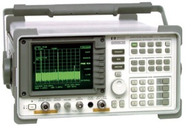
|
|
Email me:eric@satsig.net |