|
|

| SatSig Topics Index › HughesNet and Hughes HX VSATs › HX TXcode9 AFG |
SatSig topic: HX TXcode9 AFG(Read 25736 times) |
|
Feb 11th, 2011 at 1:29pm
|
|
Feb 11th, 2011 at 2:09pm
Your receive signal quality is good. The 91 indicates you are tuned to a satellite downlink carrier set on the manual commissioning configuration screen (frequency and symbol rate). Well done getting that far. The polarisation adjustment amount may still need tweeking a bit but this should not affect your ability to now send some sort of signal back to the hub. Typical transmit problems: Bad connector Warning: Always power off at the mains wall switch before interfering with the coax cables. Leave the low voltage multiway DC power cable from the power supply module to the modem permanently connected. The centre pin wire at the F connector should stick out about 1.5mm proud of the rim. When connected up make sure the pin and centre of the cable are not pushed back. The pin must actually go smoothly into the hole. The cable braid must make good contact with the plug outer body. Configuration Check all the IP addresses etc as per your pdf installation instructions for your site ID. If you are not transmitting it may be because the hub cannot send messages to your specific modem (so as to tell the modem to transmit) due to wrong IP address, wrong site ID, misunderstanding about which satellite network or similar. If Bentley Walker sends a command to try to reset your modem, can you observe the LEDs and tell them if anything happens ? If BW sends such commands and nothing happens at your end then there is some problem on your receive configuration, such as wrong IP addresses or there is misunderstanding about your site ID, or what network or satellite. Assembly/hardware The transmit module has two connectors at the rear end. The one marked IFL is the one for the cable to the modem. If this is an old, previously working, site, or you have installation instructions or configuration settings from someone else, contact Bentley Walker telling them your modem serial number and LNB model and type number, and your new lat/long location. Best regards, Eric. |
|
Feb 11th, 2011 at 2:45pm
Have you tried to force ranging yet? If no, open a browser to https://192.168.0.1/fs/advanced/advanced.html and look at the left hand column. Click on Installation, and find Force Ranging on the drop down list. Click it. When a pop-up window appears, click on "Start Ranging". On otherwise healthy systems, the process should ordinarily complete in under 90 seconds. //greg// |
|
Feb 11th, 2011 at 3:11pm
I am very sorry to hear of the difficulties you are experiencing with regard to your VSAT connection. If, in spite of the very helpful advice you have received thus far, you continue to experience difficulties then please raise a trouble ticket via our on-line ticketing system: https://62.49.2.48/sitehelpdesk/user/log.asp This will allow for a common frame of reference between yourself and the entire team of support staff. Regards, Dan. Bentley Walker Technical Support. |
|
Feb 12th, 2011 at 4:06am
 . I'm working on this system on behalf of the account holder. . I'm working on this system on behalf of the account holder. My satellite operators seem to think the polarization is the issue. But as I mentioned I've tried for hours just messing with the polarization and still had the same issue mentioned in my original post. Dan, I will make sure the account holder logs onto Bentley Walker and submits a trouble ticket. He hasn't mentioned anything about having a Login ID or password which raises a flag for me. Maybe he hasn't finished setting up his account so could we be missing some informaiton neccessary for setting up our system? We have a SiteID but that is the only thing he has really mentioned with regard to his account. Eric, I have NOT typed in a freq or symbol rate on the configuration screen. What config screen are you refering to? The manual commissioning? Just remember seeing a lot of screens that could be "configuration screens." Is that information something that would come with our installation instructions for our SiteID? The account holder hasn't mentioned anything about having any specific instructions for our site...these instructions would also have the IP configs needed for the modem as well? I dont have these and I dont think the account holder is tracking these as well. I will also check the power supply and insure the pin and cable have good connection. We are using equipment that was perviously in system at a different site. We will double check with Bentley Walker and provide them our moden SN and LNB model type and number. Like I said I dont think the account holder has recieved anything specific instructions for our site. BW provided us with what bird (SESAT2) we were shooting at and what azmth, elev, and pol we needed to be at in order to lock onto the bird. I used that information with a bit of research and trial and error to reach a signal strength of 91. Greg, Please describe how the system should be grounded. I've noticed the two COAX connections on the trasmitter. The one IFL to the modem and the other, GRD. Is that for ground? Please explain IDU, cable path, and ODU and how they relate to grounding. I've tried force ranging, but it can't even attempt due to the fact that the trasmitter is adjusting for optimal networking (TXcode9). We have about 1ft of snow on the ground and more coming but dispite the weather we still have a signal strength between 88-91. I think we are close to getting this thing up and running. Thanks for the help! |
|
Feb 12th, 2011 at 4:54am
Similarly, the antenna bracket should then be bonded to the antenna mast/pole (which is presumably metal). This is because the powder coat paint common to most antenna metal parts acts as an insulator. Penetrating to bare metal ensures both competent signal ground and lightning protection. Then the mast/pole itself should be connected with a length of (minimum) 10AWG solid copper ground wire. One end to the mast/pole obviously, the other to common ground. IDU stands for InDoor Unit; the modem and power adapter. The IDU should be grounded via the 3rd prong on the power adapter electrical plug. 3 to 2 adapters should not be used. What ever serves as an electrical grounding point for the IDU is considered the common ground. It's typically a metal post driven into the ground adjacent to the power source (meter, generator, et cetera). This is where the 10ga copper ground wire should terminate as well. That puts the IDU and the ODU on the same ground potential. Makes for more reliable lightning protection. Cable block: this is a specialty coaxial ground fitting, situated in both the TX and RX cable paths. Typical location of this fitting should be near the common ground as well. Another piece of 10ga solid copper should connect this fixture to common. You've already given the IDU and ODU equal ground potential. This wire does the same for the cable path, But in this case it's not lightning related. This one provides a more reliable zero reference (signal ground). A picture of the cable block can be found here: https://www.microcenter.com/single_product_results.phtml?product_id=0264138. The cable block should have a frequency rating equal to or higher than the cable and connectors. Ideally your cable should be 3GHz solid copper center conductor, terminated in 3GHz exterior grade compression connectors, grounded through a 3GHz cable block. I'm not in a position to re-create your situation with my equipment. But I've been able to over-ride a TX9 by force ranging in the past. This assumes however, that valid satellite (commissioning) parameters are installed and verified. //greg// |
|
Feb 12th, 2011 at 7:08am
We are using equipment that was previously in system at a different site. We will double check with Bentley Walker and provide them our modem SN and LNB model type and number. This will almost certainly lead to solving the problem. A typical manual commissioning configuration screen looks like this: Don't try using these parameters as they do not refer to your site 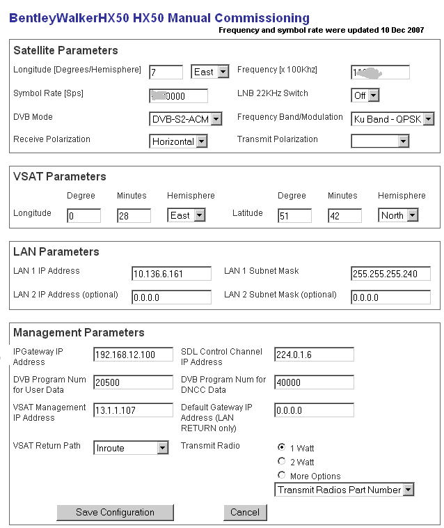 Don't change anything till you have received by email a single page pdf file from Bentley Walker with all the data for your site. Bentley Walker will need to reactivate the old site ID or delete the old Site ID and give your account holder a new Site ID. Since you have not typed in any new configuration parameters and are getting a signal of 91 you are successfully pointed at the same satellite as previously. A small adjustment of polarisation may still be necessary but this will not prevent your transmit signal getting to the hub. I believe the problem is related to the hub database and clarifying the modem ESN serial number, site ID and maybe updating the configuration settings. Best regards, Eric |
|
Feb 12th, 2011 at 9:20am
I have been assigned to your case and aim to get you up and running ASAP. However; I do require some additional details, we require a complete screenshot of your VSAT Manual Commissioning Page (configuration page), you will need to follow the below steps to reach the VSAT Manual Commissioning Page: 1) Browse to the below URL: https://192.168.0.1/fs/advanced/advanced.html 2) Select "Installation" from the menu options on the left hand side of the page (at the bottom of the list). 3) Select "Setup" 4) Select "VSAT Manual Commissioning Page" Please send the screenshot to the below email address: support@bentleywalker.com Please include the ESN number of your HX modem in the subject line of the email, also; put "ATT: Gary". Also; if possible include a photograph of the dish assembly. |
|
Feb 12th, 2011 at 12:54pm
|
|
Feb 12th, 2011 at 6:26pm
So again, if your commissioning parameters are inaccurate - like if the modem thinks it's in Minneapolis instead of XXXistan - it will blindly calculate incorrect time and distance, and subsequently never acquires the actual network timing data it needs to proceed. //greg// |
|
Feb 12th, 2011 at 7:26pm
Check that the lat and long have been put in correctly, e.g. 70 deg 5 minutes East, and 35 deg 15 minutes North. The hub also need to be told these details for their records to be correct. 1 mile, or worse, accuracy is quite adequate. Don't put the details here for security reasons. Best regards, Eric. |
|
Feb 13th, 2011 at 2:03am
|
|
Feb 13th, 2011 at 9:24am
After you click "Save configuration" do the lat long (and other details) update, as you have just typed them ? Or do the details remain stuck as per the previous owners location etc. If the config parameters are locked and can't be changed you will need to Reset to Factory default. rf command. Don't do this unless you have a) copied all the current config parameters to paper and b) have your new pdf sheet of parameters from Bentley Walker. Can Bentley Walker send a reset command to your modem and can you see it's LEDs flash in response ? If YES this will confirm to Bentley Walker that they have definitely identified which satellite and which network outlink carrier you are actually pointed at and tuned to. They can also work out from your screenshot of your config parameters what frequency and symbol rate you have and check to which satellite and network this corresponds. Best regards, Eric. |
|
Feb 13th, 2011 at 1:10pm
The modem is trying to trasmit but with a 99% failure rate...please help... |
|
Feb 13th, 2011 at 1:31pm
Once it starts communicating with the hub it will download new software and the power LED will stop flashing. Your polarisation setting sounds good: There are two different polarisation starting positions: 1. LNB sticking upwards or downwards. 2. LNB sticking out sideways (either side has the same effect). You started on the left (as viewed facing forwards towards the satellite in the sky) From either of these starting positions turn the polarisation +22 deg clockwise, as viewed facing forwards towards the satellite in the sky. One final polarisation setting will work perfectly, the other (90 deg away) not at all. If you have a discrete LNB module, such as NJR2184, with rectangular waveguide interface and four attach screws and then when the LNB is sticking out sideways you are receiving vertical name polarisation. If you have a Universal integrated LNB/OMT module (HughesNet part number PN 1501882-0002) then when the LNB F connector is sticking out sideways you are receiving horizontal name polarisation. === Since the modem has reverted to its default software it is possible that you have either done a reset to factory default or that the hub has managed to tell it so. Also, does 99% failure suggest that 1 burst actually got through?. If so, check the transmit cable connections again, the braid must make good contact at either end and the centre pin wire must be clean and long enough to stick out about 1.5mm proud of the rim of the plug. When screwing in make sure the center wire really does go into the hole and does not push back. If the old wire end was burned the springs inside the socket will need cleaning. Try using a 6 inch length of spare centre wire and gently poke the end in and out 20 times. Best regards, Eric. |
|
Feb 13th, 2011 at 2:01pm
Our modem's power LED light started flashing today...that cant be good, right? Good and bad. As Eric said, it's the modem telling you that it's awaiting a firmware update from the provider. But unfortunately you need your transmit working to actually receive that update (it's an ACK/NACK thing). So from now on, that Power LED will continue to blink until such time as you actually get the modem registered.One thing that I don't recall being addressed here, is the modem power adapter. It takes AC from a 3 wire source and converts it to the various DC voltages required by the IDU and the ODU. The modem in turn forwards DC power (via the coaxial cable) to the ODU to operate the LNB and transmitter components. If the transmitter is not getting enough DC power from the modem, the transmit signal to the satellite will be weak. This can be caused by a failing power adapter, the WRONG power adapter, or a substandard IFL (cable path). Hughes has a wide range of power adapters (15w to 80w), I'd expect you to need one of the higher end units; at least 64 watts, perhaps even 80. So that brings me to ask if you're using an AC/DC power adapter (like I described above), or the optional DC power supply? I don't have any HX50 hardware here. But if you provide part numbers (power supply and all those you can find at the dish), perhaps Eric and/or Bentley Walker can determine if your equipment is getting sufficient electrical power. I'm in the process of sending Hughes power supply rules right now. Oh, that list by the way - is technically published for stateside use. But it's still applicable to your case, as the HN series modems essentially parallel the HX series in other parts of the world. //greg// |
|
Feb 13th, 2011 at 6:08pm
for compatibility table for power supply modues. Best regards, Eric |
|
Feb 14th, 2011 at 1:56am
I'm glad to hear about the power light blinking being normal. I will check the modem later this morning (its not in my tent) and see if it downloaded any new updates. It has been updating itself throughout the process. So maybe it somehow got reset and is now trying to update itself. I will check on the software/firmware dates. Eric, I will check which LNB we have and maybe try starting the LNB at the 3 o-clock and see if that makes any difference. We have checked the cables and swapped TX and RX and still get the same problems so I don't think it is a cable issue. Greg, I will check and see what type of power supply we have. I never thought about it but we are using about a 75-85ft COAX cable so maybe we arent pushing enought power to trasmit?? Just a guess... |
|
Feb 14th, 2011 at 8:42am
I will check which LNB we have and maybe try starting the LNB at the 3 o-clock and see if that makes any difference. The 9 o'clock and 3 o'clock polarisation start positions give the same result. It won't make any difference which of these two start positions you choose. From either side position apply 22 deg clockwise adjustment amount, as viewed facing forwards towards the satellite in the sky. At some locations a large polarisation adjustment amount, such as +/-80 deg, is required. In such cases, if you find that the LNB hits the metal base of the yoke before the adjustment amount is achieved then start on the other side. The transmit cable carries significant DC power current to the BUC so the connections and cable quality are critical. Check for corrosion that may have caused the sheath to degrade for several feet under the outer insulation. If you use a new cable, fill the outdoor connector with dielectric electronic grade silicone grease and seal the finished connection with weatherproof tape. This is really important. Read more: https://www.satsig.net/bentley-walker/hn7000s/Hughesnet-Measuring-IFL-Resistance... https://www.satsig.net/bentley-walker/hn7000s/Hughesnet-Approved-Cable-List.pdf Best regards, Eric. |
|
Feb 14th, 2011 at 11:41am
Greg, Well, low voltage from the power adapter is one of the things that can cause reduced the transmitters RF output power. As can a substandard IFL (cable) path. That's why I forwarded additional Hughes installation documents for Eric to post (I'm in the USA, Eric's in the UK). Hughes Approved Cable list is dated, but should give you an idea of the minimum cable build standards, and the IFL Resistance measurement should get you started making sure none of your cable segments and components are bottle-necking your TX signal. I will check and see what type of power supply we have. I never thought about it but we are using about a 75-85ft COAX cable so maybe we arent pushing enough power to transmit?? Just a guess... If it helps, loop testing can save time. For example; my cable run to a 2w transmitter (1035817-0001) is about 110 feet of 3GHz solid copper with matching connectors and ground block. Grounding is as described previously. I start by labeling the Sat In and Sat Out cables at the backside of the modem. I remove them from the modem, then connect the two cable ends together with a 3 GHz barrel connector. At the dish, I remove both cables and measure resistance between one connector body and its center conductor. The result should be an open (~0 ohms). the two connector bodies. Next measure between the TX and RX connector bodies. That checks resistance via the cable sheathing. After recording the result, I check resistance between the TX and RX center conductors. Remember, this is over my 220' loop. I got 1.6 ohms and 1.5 ohms respectively, well within Hughes parameters for one 110' cable. Given that result, there was no need to test the individual segments. But if the loop test is at or over minimum spec, you remove the barrel connector and start individual segment testing to isolate the bottleneck. //greg// |
|
Feb 15th, 2011 at 12:17pm
|
|
Feb 19th, 2011 at 10:31am
I am very glad to hear that your site is now up and running, and I gather from my colleagues that the issue was simply related to polarisation. It's cases such as these which really prove that the old adage "A picture is worth a thousand words" could not be any more true! Regards & best wishes, -Dan & the Bentley Walker Tech Team. |
|
Email me:eric@satsig.net |