|
|

| SatSig Topics Index › General and other topics › Two transmit frequency in one dish |
SatSig topic: Two transmit frequency in one dish(Read 11029 times) |
|
Aug 18th, 2011 at 8:10am
Is it possible to transmit two frequency on a single satellite dish? What equipments to I have to add to my present set-up that transmit on single frequency? My set-up is Modulator-Upconverter-HPA-Satellite dish. thanks, ken u. |
|
Aug 18th, 2011 at 9:40am
The specificied rated power for a BUC/HPA refers to its use in single carrier operation. For example, if you have a 10W rated HPA and are transmitting one 9W carrier that is fine. If you want to upgrade and transmit two 9W carriers you need a 40W rated HPA. The amplifier is backed off by -3.4 dB, and is operated at 18W, just below half its rated output for single carrier operation (40W). Ask BUC/HPA manufacturers about pre-distortion and feedback type linearisers and the ability of their BUC/HPA designs to operate with multiple carriers. If you intend to transmit 8PSK or 16QAM linearity is particularly important. Consider the costs of the higher power amplifier, electricity, cooling etc compared with a second antenna and a low power HPA operating near saturation. If at all possible operate with one carrier only and partition the traffic using a router, for example. With a modulator/upconverter/HPA configuration, if you need an extra transmit carrier.. If the extra carrier is close by, within the bandwidth of the upconverter (e.g. 40 MHz bandwidth for 70 MHz upconverter), then you need a 70 MHz combiner and two modulators. If the extra carrier is far away, outside the bandwidth of the upconverter (e.g. 80 MHz bandwidth for 140 MHz upconverter), then you need a new upconverter and a 6 GHz or 14 GHz combiner and two modulators and two upconverters. If you are using an L band upconverter then the bandwidth will be wide enough so that you only need a extra modulator and L band combiner. Note that if you put multiple carriers through an upconverter (or any IF amplifer device, TX or RX, at the teleport) then the levels through the upconverter must be carefully adjusted to avoid intermodulation. It is possible to combine multiple BUCs/HPAs together using passive combiners, which lose 3 dB as heat, at each pairing stage or using waveguide cavity filter combiners which are very expensive (as used in the satellites). In any case of more than one carriers transmitted through one BUC or HPA you must have a high loss cross-waveguide monitor coupler on the 6/14 GHz output of the BUC/HPA and a spectrum analyser able to monitor and plot the BUC/HPA output spectrum. Consider if you can operate your second carrier on the opposite polarisation. If you have a 4 port (2 transmit and 2 receive waveguides) feed then you can use a second BUC/HPA into the other transmit port and still retain the preferable arrangelment of one carrier per amplifer arrangement. Best regards, Eric. |
|
Aug 18th, 2011 at 4:15pm
I will be using two modulator, two upconverter and two HPA, the two outputs of HPA will be connected to a diplexer which the other end is connected to one of the Tx port of my dish. Or sir do you have other suggestion set-up. thanks, ken u. |
|
Aug 18th, 2011 at 7:03pm
1. A 3 dB hybrid coupler and dummy load. The coupler has 4 ports. Two ports for inputs, one port for the merged output and one port for the dummy load. Note that you will lose half your entire power in the dummy load. The use of a device like that below will allow two BUCs to be operated simultaneously, each with a different transmit carrier from its own modem and the output at 14 GHz combined.  Read more: https://www.atmmicrowave.com/wave-combiner.html Unfortunately there is a 3 dB loss, so only half of the power from each BUC will reach the feed. Choose a coupler that works over the bandwidth you require.  You also need a suitably rated finned dummy load to terminate the other half of the total power at the unused port. Read more: https://www.credowan.co.uk/waveguide-loads.htm Search Google for waveguide couplers and waveguide loads. Explain to the suppliers exactly what you want to do and get their assurance as to suitability of the proposed parts. 2. A filter combiner or diplexer This works if the carriers from the two HPAs are well apart in frequency. There is minimal dB loss but high cost. This is the solution used on satellites to combine the output from several HPAs into one downlink beam polarisation. The principle is the same as that used for a co-pol VSAT feed where transmit and receive are on the same polarisation. For VSAT operation the two waveguides operate far apart in frequency, like 3.4-4.2 GHz and 5.9-6.4 GHz. Trying to operate say 6.3-6.4 and 6.6-6.7 is far more difficult and expensive. A band-pass/band-stop filter is needed in each HPA port and these filters also need to block the other frequency. These filters may well be very expensive. If you really need two carriers and have a 4 port feed what not ask the satellite operatior if they can lease you some capacity on the other polariation, then you can connect the second HPA direct to the other feed TX port? Best regards, Eric. |
|
Aug 19th, 2011 at 2:13am
What's the use of the other output port of the 3 db coupler where we need to put a dummy load? Do it contain the same signal as the other output port? And can I use this even I am transmitting the two carrier near to each other? Do the satellite recognize my transmit signal as two individual carrier when I use it? I think diplexer is not on the option since I will be transmitting two carriers that are near to each other, just hundreds of megaherts away. And regarding the option of using the other input port of my feed horn can I use those two input ports on different frequency or I can only use it on the same frequency but in different polarization? thanks, ken u |
|
Aug 19th, 2011 at 10:19am
It is of no use, just wastes half of the power of both input signals. Do it contain the same signal as the other output port? Yes. It contains half of one signal and half of the other. And can I use this even I am transmitting the two carrier near to each other? Yes. The 3 dB coupler works very well if the carriers are close together (or far apart). This is why the 3 dB coupler is used. It is very flexible and wide band. You can change carrier frequencies in future with no problems. Do the satellite recognize my transmit signal as two individual carrier when I use it? Yes, the satellies see both signals quite clearly, but at half power. I think diplexer is not on the option since I will be transmitting two carriers that are near to each other, just hundreds of megaherts away. The diplexer filter combiner option is not feasible if the carriers are close together. It is far too expensive and and can't be modified or adapted in future. If you change carrier frequencies in the future you likely need to buy a new diplexer filter. And regarding the option of using the other input port of my feed horn can I use those two input ports on different frequency or I can only use it on the same frequency but in different polarization? The two transmit ports on the 4 port feed are intended to be used for transmitting on two different polarisations. Normally you connect one HPA to each port. You need to lease capacity on the satellite on both polarisation uplink transponders. You could transmit one carrier on each polarisation with each HPA operating up to full power with no losses and no problem. The most obvious solution for two carriers on the same polarisation is to merge the signals together (at 70, 140 MHz or L band or 6/14 GHz) before the HPA and use a 40W HPA to transmit two 10W carriers. Note the -3 dB back off to minimise intermodulation interference. Alternatively use two antennas and two 10W HPAs. Best option is to transmit one carrier only at 20W, using 20W HPA. Best regards, Eric. |
|
Aug 19th, 2011 at 2:49pm
This sounds great, how will this be possible? I don't know if this is correct, I will merge outputs of two modulators then convert it using the upconverter then amplified it by using HPA (i think i will be having no problem with the power since my HPA is rated 700W). But sir how will I merge the two outputs of the modulator to connect it to the upconverter? thanks, ken u. |
|
Aug 19th, 2011 at 3:56pm
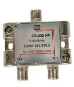 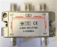 Examples of 2 and 4 way splitter / combiners. Make sure you don't buy the active version with amplifiers included. You want the passive version that will work either way, as a splitter or combiner. Some such devices are advertised at 5 - 2150 MHz, so would work in the 70 and 140 MHz IF bands as well. If you get a 4 port device terminate all the unused input ports with 75 ohm dummy loads. If you have a 700W HPA you can probaly operate two equal level carriers, each at 125W. The total power is then 350W and the output is 3 db backed off from its rated maximum. The intermodulation interference levels should be acceptable (unless you transmit two unmodulated CW carriers). Check and plot the output spectrum and consult the satellite operator. You may be able to increase the operating point a little and still be acceptable. It depends on your carrier bandwidths and the HPA specification and its linearity near saturation. Best regards, Eric. |
|
Aug 19th, 2011 at 4:20pm
How will I use that splitter/combiner? Base on the first picture, will I connect the outputs of the modulator on the 2 output ports and the input of the upconverter to the input port? I have here a splitter range 5-1000MHz and I am using it to split signal from LNB, can I use it as a combiner? And what frequency will I use on the modulators? Is it ok to use 70 MHz on both signal? thanks, ken u |
|
Aug 19th, 2011 at 5:09pm
If you are merging the outputs from two 70 MHz modulators, note the range of output frequencies from the modulators. The modulators may be tuneable so as to set the carrier centre frequency anywhere between 50 to 90 MHz. e.g. One 10 MHz wide carrier centred at 57 MHz and one 15 MHz wide carrier centered at 74.5 MHz. The carriers must not overlap and the difference between the centre frequencies must correspond to what has been approved by the satellite operator. Check your maths carefully and draw out the complete spectrum on paper till you are certain. The next step is to set the upconverter so as to put the carriers at the right frequency in the 6 or 14 GHz bands. Make sure you understand how the upconverter frequency setting works. The displayed and keyed input figure may correspond to the result frequency assuming a 70 MHz centre frequency on the input. Think about that carefully. Note if you have 4 way 70 MHz combiner followed by a 2 way 70 MHz splitter you create yourself a monitor point of the upconverter input. Terminate when not in use. A 700W HPA typically already has a low level monitor point on its output for a spectrum analyser. Best regards, Eric. |
|
Email me:eric@satsig.net |