The explanation, which is probably not relevent in this case, is as follows:
There is a single big main beam shaped like a bell or parabola, but surrounding this is the first sidelobe ring, typically 10 to 15 dB lower. Many lower level sidelobes rings exist further out.
If you make an antenna pattern cut across the main beam you see a picture like that on the left, below:
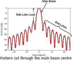
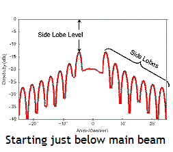
The above (left) is the normal situation and it is quite easy to work out where to move the antenna to peak up.
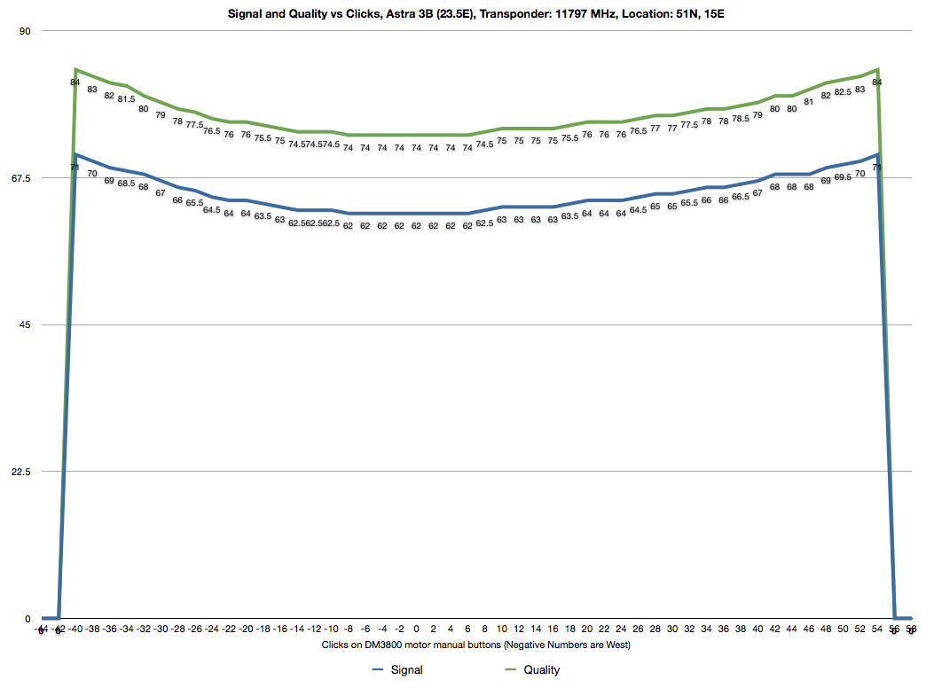
There is a special case however to be aware of, particularly with large antennas: You see two similar height 'main' beams, and this pattern is similar in both azimuth and elevation. See right hand picture. Why ?
The reason is that the nearest you are getting to the main beam is when you are in the central low trough (first null) between the main beam and the first sidelobe ring. When you 'peak up' you are in fact 45 deg away from the main beam and sitting on the top of the first sidelobe ring, in one of four possible 45 deg quadrant positions.
As you move, you simply cut through the first sidelobe ring in two places and miss the main beam altogether. The same applies when you do the azimuth or elevation cut. Think of potentially moving in a full square around the main beam, missing it all the way!
The cure is to put the antenna into the bottom of the null between the two approximately equal first sidelobe peaks and then sweeping the antenna at right angles. You will then get dramatic improvement as you find the main beam itself.
The above phenomena is very visible on large teleport dishes where the receive system is likely to work suprisingly well, even if the dish gain is 15 dB low, when peaked on the first sidelobe.
In the case of a small antenna having two such obvious peaks is a mystery to me.
I would try:
a. Check out the above (improbable) theory !
b. Check the front rim of the dish is flat using the crossed threads test. Pull the two threads tight and check they just touch in the middle.
c. Optimise the polarisation. Turn the feed one way and the other, until severely degraded and measured signal quality levels are noted. Record the angle. Repeat going the other way, and then half the angle between the two equally degraded points. The ASTRA satellite polarisation may differ from calculation (e.g. 7 deg error?).
Note:
Severe distortion of the dish shape could result in a double hump main beam.
Severe distortion of the dish shape or out of focus feed distance or feed position could result in high sidelobes and adjacent satellite interference, where the first sidelobe hits an adjacent satellite.
Poor polarisation adjustment could result in x-pol interference being severe on axis. Signal power level wou