|
Dec 16th, 2015 at 6:51pm
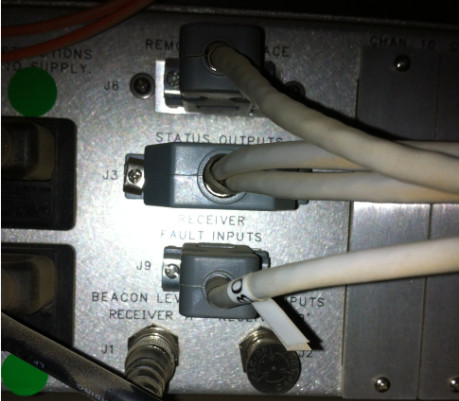
I can see the plug going into J9 on the AUPC.
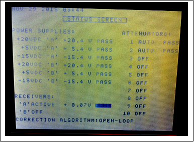
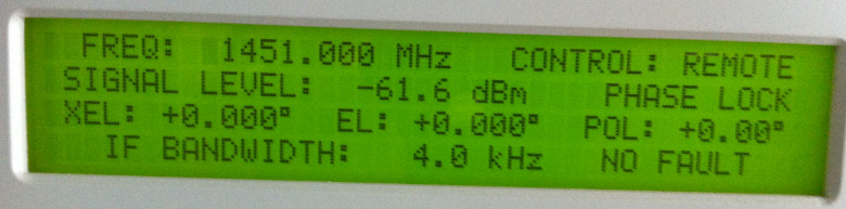
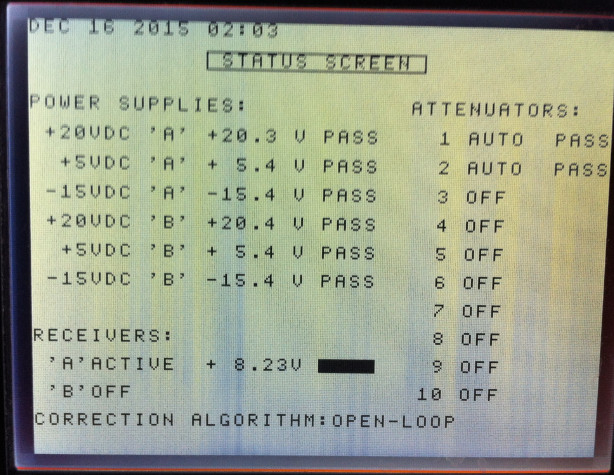
I note the receiver is working well. Power is good. Signal is locked. Signal level as shown on the AUPC 8.23 volts looks good. It would give you confidence if moving the antenna causes this voltage to change exactly as you expect. Is there a calibration scale like 1 volt = 2 dB or 1 volt=3dB .. ?
You could test, using a calibrated switchable attenuator, 1, 2, 3, 5, 10, 20 dB on the beacon receiver input. The output voltage should go down by the equivalent amounts. Turn off the UPC effect while you do such a test.
Read the receiver manual to check that -61.6 dBm is a reasonable input level. You need about 20 dB linear dynamic range down from this. The input level to the beacon receiver depends on where it is connected in the L band splitter distribution system.
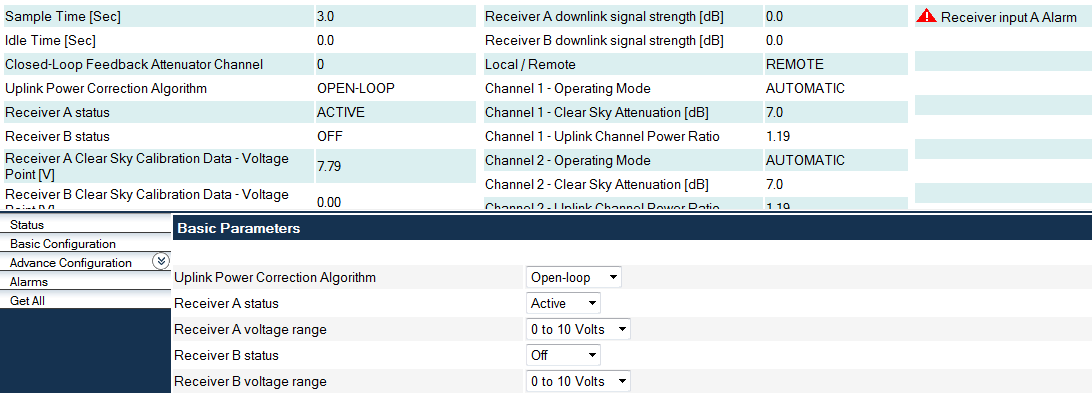
If any receiver fault (loss of power, loss of signal lock) occurs there should be a contact open or contact closure on a pair of wires which should come from the receiver (possibly J11?) to the AUPC (J9).
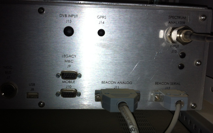
The other end of the cable to input J9 appears to be connected from Beacon Analogue output plug J11 on the receiver. Cable #30. There are two cables, the other cable is presumably the coax, carrying the analogue 0 to +10 volts.
Read the receiver manual to find out what its alarm output contacts do. The receiver contacts outputs may be connected to pins 1,2 or 4,5 or the alarm may be opposite sense, e.g. open circuit instead of closed circuit or vice versa. There may even be a configuration in the receiver so that a fault condition causes open or closed circuit on the alarm output.
|