|
Apr 30th, 2026 at 12:09pm
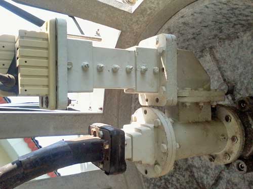
Here is a similar Ku band arrangement.

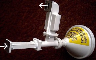
Example VSAT feed assembly with transmit and receive ports. Ku band feed with OMT and transmit reject filter and transmit bandpass filter.
The receive LNB is connected at the top. The transmit BUC is connected at lower left. The straight through transmit band-pass filter (on the left, 14-14.5 GHz) is designed to stop spurious transmit signals such as 28 GHz getting through to the satellite.
The receive transmit reject filter (shown upwards) stops the 14-14.5 signals getting throuth to the lNB, receiving 12.5 - 12.75 GHz. This filter needs to be low loss and its insertion degrades the noise temperature of the receive system.
Reference: Ku Filter /OMT assembly p/n 718312 Model : 0800-2598 and feed horn Model 0800-1375.
For mounting, the transmit module must be attached at the left and the LNB at the top.
|