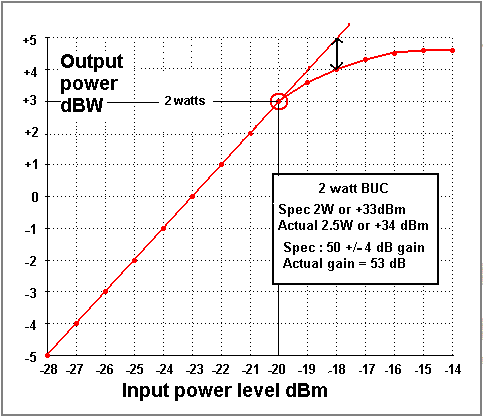
Plot several points down the linear portion of the curve, approx -20, -15, -10. -5 dB and draw a straight line through these points and extend the line upwards.
Plot the measurements graph more carefully between -5 and +5, in 1 dB steps, and then look to see where the vertical scale gap reaches 1 dB spacing. This is the -1 dB gain compression point.
See example BUC input/output transfer characteristic curve below:

Measurements should be made with a CW (sinewave) carrier.
The reasons for backing off an amplifier are to maintain a high signal quality, avoiding the amplitude and phase distortion caused by operating at or above saturation and also to avoid permanent damage to the BUC transistors due to excessive current and voltages at the peaks of a digitally modulated signal. A digitally modulated carrier has a random noise type spectrum and has a high peak to mean voltage ratio, much higher than for a sine wave.
More significant output back offs, like -3.5 dB, are necessary if an amplifier is used to transmit more than one carrier, otherwise unacceptable intermodulation interference to adjacent and other carriers is caused. This applies particularly to main teleport antennas transmitting multiple carriers and also to satellite transponder downlinks where the transponder is operating multiple carriers. A satellite transponder downlink operating a single carrier, e.g. 27 Msps TV or 27 Msps VSAT outlink, operates typically about 0.5 dB below the -1 dB compression point. Satellites used predominately for TV may have on-board automatic gain control (AGC) so that the output carrier stays at a constant accurate level, even if the uplink suffers level variations due to rain, scintillation or uplink dish tracking error.
Best regards, Eric.


