Advertisment: Broadband via satellite
Advertisment: Worldwide satellite services from Ground Control Company

www.satsig.net

Satellite Internet Forum.

Welcome, Guest.        Forum rules.
      Home            Login            Register          
Pages: 1

How to direct and align dish in Saudi Arabia ?

(Read 18720 times)
Ex Member
Ex Member


Oct 13th, 2006 at 1:19pm  
Hi, I'm seeking help on to what direction I need to direct my dish and how to align it.
I have iDirect 3100 and I should aim to NSS 6.
My location is in Saudi Arabia, eastern province near Jubail city.
Latitude: 26.6 N
Longitude: 49.9 E

Apprciate your urgent help and support.

Thank and regards,
CzAinAb
Back to top
« Last Edit: Oct 18th, 2006 at 8:56am by Admin1 »  
 
IP Logged
 
USN - Retired
YaBB Moderator
★★★★★
Offline


Posts: 837
Kentucky (USA)
Reply #1 - Oct 13th, 2006 at 1:35pm  
Perhaps you are unaware of the many satellite pointing angle utilities and online calculators available on the Internet. If not, let me introduce you to one right here at SatSig: https://www.satsig.net/ssazelm.htm

//greg//

The lat/long finder and dish pointing calculator below is a good start if you are in the Middle East area.  It is initially centered on Iraq so just need to push the map up a bit to find Saudi Arabia.
https://www.satsig.net/maps/satellite-dish-pointing-iraq.htm

I have edited the lat long above for your privacy by reducing the accuracy since I could clearly identify your roof and see the cars in the road.
wxw
Back to top
« Last Edit: Oct 18th, 2006 at 8:58am by Admin1 »  

USN (Ret)
 
IP Logged
 
Ex Member
Ex Member


Reply #2 - Oct 14th, 2006 at 12:03pm  
Thanks. I did calculated the direction. But I'm afraid that the way I assembled the BUC and LNB to the feedhorn is not correct ? since I'm not getting the signal with my site meter ?!
is there any guide for assembling BUC & LNB using Chanel Master dish.

Thanks again and appreciate any help.
Back to top
« Last Edit: Oct 18th, 2006 at 8:59am by Admin1 »  
 
IP Logged
 
Eric Johnston
Senior Member
★★★
Offline


Posts: 2109
Reply #3 - Oct 14th, 2006 at 1:31pm  
Please take several digital photos or the LNB/BUC/Feed assembly, including close ups, from various directions and send them to me at eric@satsig.net

Include an extra picture takem from over the back top of the dish facing forwards towards the satellite.

Best regards, Eric.
Back to top
 
 
IP Logged
 
Ex Member
Ex Member


Reply #4 - Oct 17th, 2006 at 1:53pm  
Hello, I've sent several pictures for my dish assembly also please find em here as well.
Appreciate your usual upmost help.

...

...

...

...

...

...


Regards.
Back to top
 
 
IP Logged
 
Admin1
YaBB Admin
★★★★★
Offline


Posts: 1203
Reply #5 - Oct 17th, 2006 at 9:00pm  
The dish pointing angles in your case, for NSS6 satellite at 95 deg east, are:

Elevation = 31.8
Azimuth = 112.1 magnetic (approx 20 deg to the right of due east, where the sun rises.)
Polarisation = -54.7 deg.

First polarisation.   You need to find out from your service provider what your downlink polarisation is called.   It may be called horizontal or vertical.   The procedure is to set your polarisation to the correct starting position.  If the name is horizontal, you need to set the feed rotation so that the LNB is at the top. The broad faces of the rectangular waveguide are then on either side - this is defined as horizontal polarisation.  If you are told to use vertical polarisation then set the LNB sticking out on the side.

Having set the starting position you must then adjust the polarisation 55 deg anticlockwise, as viewed from behind the dish and while facing towards the satellite.
...
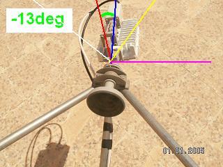
The image above shows a horizontal polarisation start position (LNB at the top) plus an adjustment of only 13 deg anticlockwise.  The blue line is my idea of straight up and the red line shows the LNB turned 13 deg anticlockwise.  

If you are trying to get horizontal polarisation you need to turn it further to the left, as per the white line.

If you are trying to get vertical polarisation then the starting angle is with the LNB sideways at the pink line and the final setting after 57 deg anticlockwise adjustment is with the LNB at the yellow line.

If you are out of communication with the hub you can try with the LNB at the white and yellow lines.  It may be time consuming but one position will work perfectly and on the other you will never find the satellite.

Now elevation angle.

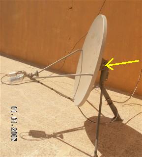
Referring to this image below.
...
The big pole tube behind the dish should be vertical - exactly upright.  Then set the required 32 deg elevation angle using the scale marked by the yellow arrow.  There may be a tick mark on the metal, or the bolt defines the reference mark or it may be the edge of the metal through the slot that is the reference mark.  Read the instructions if any.  Someone who knows this dish type may be able to say what is the reference mark to use with the scale.

Aim the dish approx south east.   Swing boldly from east to south and you will find the satellite on the first swing.  The modem receive LED will go green.   Find the bit error rate or ebno readout in the software.   Record the values.   Spend at least 60 minutes peaking up using a spanner, turning in 1/2 turn increments.  Make a movement and then a measurement.  Be patient, allow several minutes for each adjustment and measurement.  Move step by step in the right direction, then back to the peak. In elevation there is probably no backlash.  In azimuth, find the peak while driving one way, then go right back and start again, due to backlash problems.

As shown, the beam elevation angle is somewhere between 35 and 41 deg, so come down several degrees.

Do wrap the F connectors with self amalgamating tape to prevent water corrosion.  During the day the air in the cable heats up and expands and comes out a little.  At night the air inside the cable cools, contracts and sucks in cool damp air which condenses inside. Electronic grade silicone contact protection grease on the centre pin and scrunched braid won't do any harm.

Best regards, Eric.


Back to top
« Last Edit: Oct 18th, 2006 at 8:55am by Admin1 »  
WWW  
IP Logged
 
Ex Member
Ex Member


Reply #6 - Oct 18th, 2006 at 12:36pm  
Thanks for the great help. I will try it out and keep result posted.


Thanks & regards.
Back to top
 
 
IP Logged
 
Ex Member
Ex Member


Reply #7 - Oct 22nd, 2006 at 1:31pm  
Hi Eric and every one.

I was able to aim NSS 6 and get singal that measure 16.5 volts. And that was great achievment !!. The feedhorn is almost in the direction of the yellow line as per Eric diagram (thanks Eric for help).

Now when I called my NOC to do test frequency test for BUC they asked me to do littile adjustment. They asked to turn horn 5 degrees anti-clockwise then 3 clockwise etc... I ended up losing the signal. Then they asked to re-point and call again. This funny. I'm waiting for them now and will see. Smiley

Question: I have a big and tall tower that is away around 400 meters from my site location but I noticed that I'm almost directing towards it. Will this cause signal blockage ?


Best Regards.
Back to top
 
 
IP Logged
 
Eric Johnston
Senior Member
★★★
Offline


Posts: 2109
Reply #8 - Oct 22nd, 2006 at 7:42pm  
Well done.

A point of clarification: you say that the feedhorn is in the direction of the yellow line.  I think you mean that you have rotated the feed assembly so that the LNB is on the yellow line.  This means you are receiving the  downlink polarisation called "vertical" and have made an adjustment of -57 deg anticlockwise.

The polarisation needs to be adjusted to 1 deg accuracy and this is why the NOC asks you to make adjustments.  When you do this you need to crouch low down at the side of the antenna and adjust the rotation of the feed assembly with your arms underneath it.  You must not have any body part between the feed horn and the dish or obstruct the beam towards the satellite.  If they ask you to turn the feed 5 deg, do so and then wait.  It may take the NOC 30 seconds to get a good reading, similarly after the next adjustment.  They are trying to talk you into the middle of a very narrow and deep null, where making the measurements is difficult.

Regarding loss of signal.  

You may not have had the dish pointing tightened up properly and accidentally jogged it a little in azimuth or elevation.  Having found the satellite it normally takes 10 - 20 minutes of further adjustments to find the exact beam centre.  This is important since the transmit beam is narrower than the receive beam.   Tightening the nuts tends to mispoint the dish.  When you finally tighten the azimuth clamp, the elevation will typically rise slighty and need readjusting.   Another reason for loss of signal may be that your F connectors are loose.   The F connector centre pins should stick out 2mm and should properly insert into the socket holes.  The connectors must be covered with self amalgamating tape or similar to keep out moisture.

The bottom of the mount legs should be held fixed with small rawl-bolts or fixed to the concrete in some way.  

Rotating the polarisation by 5 deg will make little difference to the wanted co-pol signal as the peak is very broad.   You need to rotate by a much larger angle, like 15 to 45 deg to get a noticable reduction in signal level.  If there is no signal on the opposite polarisation then a 45 deg rotation will only produce a 3 dB reduction.  This is why polarisation is best pre-set approximately by calculation.  If you try to do it by measurement you need to wrap a strip of paper round, and degrade the signal substantially one way.  Mark the paper and note the exact degraded quality(volts in your case).   Rotate the feed on the opposite side of the max and find the exact same degraded level.  Mark the paper and halve the distance.  Repeat several times and average the centre point is necessary.  You can see why it is a lot easier to let the NOC make cross-pol measurements and talk you into the null.

Regarding possible obstruction of the beam.  You can get an approximate idea by putting your eye behind the dish, in the middle, at the lower edge and sighting along the line of the feed support arm.    If this goes well above the obstruction, then fine.   If it is marginal a more accurate method it to sight 32 deg elevation with an inclinometer at the height of the bottom edge of the dish.   An inclinometer made with an A4 size card, a length of cotton thread and small nut is fine.  Just mark a line at the required angle using a protractor or using the tan calculator at Start, Programs, Accessories, Calculator, View, Scientific on most PCs.    tan=opposite/adjacent.
If you attach the inclinometer card to a long strip of wood, one person can look along it while another reads the angle.

Best regards, Eric
Back to top
 
 
IP Logged
 
Ex Member
Ex Member


Reply #9 - Oct 26th, 2006 at 8:59pm  
Hello,

I have followed recommendations above. I'm having much clearer understanding of appointing now (thanks Eric). However, the problem still presists because according to my NOC, they can not receive my BUC signal though they can receive the CW test signal but actual transmission they can not. Plus, the isolation level still does not reach to acceptable level according to them it's now 18db and it should be 30db. They told me that I have problem in my dish.!! What is it ... I do not know and they did not tell me what ??!!. They could not advise me more !! and it seems I'm left alone Sad

Is 1.2M Ku Rx,Tx Channel Master type of dish ok?

Any suggestion are welcomed ...


Regards.
Back to top
 
 
IP Logged
 
USN - Retired
YaBB Moderator
★★★★★
Offline


Posts: 837
Kentucky (USA)
Reply #10 - Oct 26th, 2006 at 11:23pm  
Transmitter isolation is a product of your polarization angle; POL or SKEW or TILT, whatever your hardware provider calls it.
Assuming that you were provided a dish of sufficient gain and a properly working transmitter of adequate power, an insufficient isolation number generally suggests inaccurate pointing angles. The error is primarily in the polarization angle, but is related to Az and El as well. Did you try to rotate the feed while in contact with your NOC?

Another cause could be insufficient EIRP. Perhaps Eric can, but I'm unable to ascertain the transmitter power from the photos. It looks like a 1w unit, but I can't be sure. Even the dish could be too small, but generally provider-supplied hardware should be specific to the application.

At any rate, I believe 30 only represents threshold - and you're still 12 points shy of that. By threshold, I mean don't think the job is done when you get to 30. Keep peaking pointing angles until you can conclude there's no more improvement to be obtained. I have a 74cm dish and a 1w transmitter, and achieved an isolation figure of 39.

//greg//
Back to top
 

USN (Ret)
 
IP Logged
 
Ex Member
Ex Member


Reply #11 - Oct 27th, 2006 at 4:40am  
Thanks.

The BUC is of type NJT5037F manufactured by NJRC (https://www.njr.co.jp). Its power is 3W.

I did rotate and adjust Polrizer, Ez and El with the NOC and according to them came to perfect Cross Pol angle and they asked me to look the Polirizer which I did. Then asked to adjust Ez & El ...

I will give another try to re-appoint the dish. Though I guess I will not get any further ..! because this the 3rd or fourth time. Perhabs the problem is the dish or the dish size. But there are other installations in my same city with same dish !!.  Is there away to test if those BUC & LNB ok or might be defective. Or maybe I need the way I assembled them to the feed horn is incorrect. Maybe it wouldbe different if I flip them !! or flip one of them. Or the antenna type (Channel Master) is not compatible.

How do I find out any point to start with.


Regards.

Back to top
 
 
IP Logged
 
USN - Retired
YaBB Moderator
★★★★★
Offline


Posts: 837
Kentucky (USA)
Reply #12 - Oct 27th, 2006 at 5:15am  
1.2m and 3w should be enough for most any consumer-grade access. Installation issues aside, pointing your type of antenna is done in a particular sequence.
1. set in rough AZ/EL/POL angles from the look angle calculator
2. adjust AZ/EL to obtain received signal level from assigned transponder
3. optimize AZ/EL for peak RSL
4. test isolation, rotating feed as directed by the NOC.
In some cases, slight adjustments to AZ/EL may be required to optimize POL. In these instances, it's cost-effective to trade off some RSL points for an increased isolation number

It's also important to note that signal level adjustments will generally lag the physical angel adjustments by 10 seconds or more. Move the dish a few millimeters at a time, waiting for a new RSL to register each time.

If none of that works, it then may be time to consider incorrect assembly or defective hardware. Oh, and I don't see any indication that your system is grounded.

//greg//
Back to top
 

USN (Ret)
 
IP Logged
 
Eric Johnston
Senior Member
★★★
Offline


Posts: 2109
Reply #13 - Oct 27th, 2006 at 9:42am  
My thoughts..

The polarisation rotation null is narrow and it is important to make very small rotation movements when adjusting.  The clamp over the feed throat will have to be slightly loose to allow this adjustment.  It must not be so loose that the BUC sags down and the feed points up towards the top of the dish.  

Focus:  The distance from the feed to the dish should be correct.   If alternative distances are possible then the focus may be wrong.  There may be rings on the outer of the tube that exactly define the distance.  If not, and the tube may be slid in and out then try the other extreme and also half way.  Make accurate receive quality measurements (volts) at each of the three positions and optimise.  

The 18dB x-pol is so bad that it is unlikely to be due to pointing error.

If it is not due to poor rotation adjustment (which may well easily explain 18dB) then I would suspect a feed problem.

The round tube from the horn back to the OMT junction must be straight.

There is a round joint between the feed horn and the OMT.   At this joint the two holes must align exactly.  It is no good if one tube is slighly offset to the side relative to the other.  Also the joint must be firmly tight, so that the flanges are flat against one another all around.   If there is a rubber O ring then it is possible that there is a gap in the metal on one side and not the other, so the tube is not exactly straight.

The inside of the tube must be clean with no lumps of silicone grease, misplaced loop of the O ring, metal parts, screw, nut, washer left inside the tube.    

At the LNB and BUC flanges there may be square gaskets, each with rectangular hole.   These rectangular holes must be aligned with the rectangular waveguides and not put at right angles.

After the NOC did the x-pol test with a clean CW carrier I am not clear if the NOC then refused to proceed further with a normal modulated carrier transmission or if they tried to make the BUC send a modulated carrier and failed to receive such a carrier.

The CW test is done on a different frequency from the normal traffic carrier frequency.  

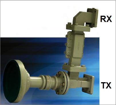
I don't know if it is of any significance but this picture shows the filter next to the OMT.
...  
The LNB must go on the end of the side arm with the filter to protect the LNB.  The small amount of 14 GHz power that goes up to the filter reflects back down and the total distance up and down may matter.

Best regards, Eric.
Back to top
« Last Edit: Oct 27th, 2006 at 4:27pm by Eric Johnston »  
 
IP Logged
 
Ex Member
Ex Member


Reply #14 - Oct 28th, 2006 at 12:35pm  
Hi,

If I'm left with vendor I might be alone ... but with you guys and your support I will never be. Thanks for all and for all recommendations and advises. Unfortunately, I will be away from this site in a biz trip for 15 days. I shall be back on November 12th and get you my response.


Regards.
Back to top
 
 
IP Logged
 
Ex Member
Ex Member


Reply #15 - Nov 25th, 2006 at 4:22pm  
Thanks every one for all support and comments. I got it right. I got it working finally ... The last comments by both USN - Retired and Eric were of great help and I managed it right this time. The problem was that the LNB arm was flipped, I just flipped back and every thing works fine.


Regards.
Back to top
 
 
IP Logged
 
Ex Member
Ex Member


Reply #16 - Dec 9th, 2006 at 8:08am  
1.2m and 3watt is much more that enough in Jubail, NSS6 has a good coverage over Jubail, with 0.96m it can work also very well, trust me i lived in Dammam and installed in it 1.2m for NSS6 and it was much more than enough and very easy to point the antenna, it was easy like pointing to Nilesat, beleive that, your problem should be either in the cables or the configurations, or pointing, reveiw it man for once and it shall be solved,

It is very usefull to use Signal Meter, mmmm am trying to get you a technichan i used to deal with, or oyu can go to any at King Saud Street and get one with his TV receiver, when he gets a very good signal, ask him to wait and check the signal with your iDirect, then if it's good try to do CW, if the problem that your NOC can't see you, then i guess you should check your BUC and.


ALSO it is very important that you have the correct GPS values (Alt, Lat, etc), not all the modems have the same Gps coordinates formats, iDirect it's different than Nera, than link start etc, and make sure you gave your ISP the correct GPS (If they Asked for it), your GPS coordinates  should be taken using GPS device, not google earth or any website, try to take the GPS next your dish and write down the values.


Also it couldbe from the tower i faced this issue with a tree before, as i can see from your picture it's not difficlt to move yor antena it's not big tripod out there. Smiley


Best Luck  Wink


Back to top
 
 
IP Logged
 
Pages: 1