Advertisment: Broadband via satellite
Advertisment: Worldwide satellite services from Ground Control Company

www.satsig.net

Satellite Internet Forum.

Welcome, Guest.        Forum rules.
      Home            Login            Register          
Pages: 1

Pointing to Panamsat 9

(Read 11770 times)
Ex Member
Ex Member


Mar 29th, 2007 at 3:36am  
Hi everybody, I'm new in this forum and in satellite technology . I hope someone could give me some assistance or suggestion.

I'm in Monterrey, Mexico, installing a Channel Master type 180 1.8 mts offset antena with a Norsat 3220 LNB and a dual-feedhorn from Chaparral (https://www.chaparral.net/feed-horns/dual-feed/), The satellite equipment it's a DSR4410 receiver/decoder from Motorola.

Finally the splitter it's a SED-778 from DX-Antenna.

The satellite I need to point it's the Panamsat9 (now Intelsat9)
58west. The site it's located at 25.82 North and 100.2344 west.

1.-To do a basic pointing a used a compass and the elevation scale from the antena ( elevation 34.66 and azimuth 115.60 from north) however I don't get any signal,
could you check if elevation and azimuth are rigth?
with only these tools it's enough to do the job?

2.-I think that the elevation scale it's compensated (offset 22.62), but how can I be sure.

3.-The Antenna was used some time before with the orinigal Ku band feed/Lnb, in order to mount the new feed we fabricate from scratch a hardware from steel and we are using the original legs, do you have any recommendation in order to be sure that the feed be at the focus?

4.-How and when I got to adjust the phase?

5.-When and why I got to adjust the scalar rings?

6.-When I start to search for the satellite I connected the coax cable direct to the LNB and the "Signal quality" in the receiver went from 40% to 65% but the "signal state" remains in "searching". After that I installed the splitter and I grounded it and then I connected one coax from the LNB to the splitter and another from here to the receiver and the "signal quality" have been in "0". Which is the right way to do this part?.

I'll really appreciate your help
Back to top
« Last Edit: Jun 11th, 2018 at 1:57pm by Admin1 »  
 
IP Logged
 
Eric Johnston
Senior Member
★★★
Offline


Posts: 2109
Reply #1 - Mar 29th, 2007 at 7:34pm  
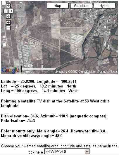
I had a look for your latitude/longitude location on page: https://www.satsig.net/maps/satellite-tv-dish-pointing-usa.htm and came up with this.
...
Your azimuth and elevation aiming looks good. You don't mention polarisation, which is -54.3 deg. It matters for PAS-9/IS-9, since that satellite uses linear polarisation for both Ku and C band.

Test the elevation scale by tipping the dish so that the front face is vertical. I guess the feed arm will then be low down in front. The elevation reading should be about 22.6 deg. The beam direction will be a line from the central bottom edge of the dish via just over the top of the feed assembly towards the satellite.

I have no idea what phase means in this context.

Scalar rings: You say your antenna is an offset type. The feed assembly will be on a long arm joined at the bottom. In this dish configuration the feed is further from the dish than would be the case if the feed was on the antenna axis, on three short equal length struts as on an axi-symmetric dish. The scalar rings can be moved to alter the radiation pattern of the feed waveguide. If the rings are back then the energy spreads wider and this is suitable for an axi-symmetric dish, with an f/d ratio like 0.3. If the rings are put forward, nearer the waveguide aperture, then the energy is more focussed, suitable for the feed being further away from the dish as in the offset design. Look closely at the feed tube. Are there ring positions marked f/d=0.2, 0.3, 0.5, 0.6, 0.8?. Offset antennas have f/d ratios like 0.6, 0.8. (f/d=focal length/diameter) Put the scalar rings towards the dish in your case. Focal length is the distance from the feed aperture to the bottom edge of the dish in an offset dish.

Polarisation. This is a two step process. Step 1. If you want to receive signals called horizontal polarisation then rotate the feed so that the broad flat faces of the rectangular LNB waveguide are on either side. The dipole radiating pin inside the LNB waveguide will be horizontal.  If you have some automatic remote control dual polarisation LNB just set it obviously "upright" so that the text on the label is readable, the cable coming out of the bottom or whatever. Step 2. This is the adjustment. Do this carefully and accurately. While facing TOWARDS the satellite rotate the feed assembly and LNB anticlockwise by 54.3 deg. (minus means anticlockwise). Then clamp the feed throat.

Splitter: You mention grounding it. Is this a double ended F connector with earthing in the middle?. If inserting this causes failure then you have either blown the receiver power supply by accidentally shorting out the DC supply or, more likely, you have bad connections. The braid must make good contact with the inside of the F plug sleeve. The centre wire must stick out 2mm so it goes deep enough into the socket.
wxw
If the splitter is a three terminal device please say and I will amend the text here.

Best regards, Eric.
Back to top
« Last Edit: Jun 11th, 2018 at 2:00pm by Admin1 »  
 
IP Logged
 
Ex Member
Ex Member


Reply #2 - Apr 3rd, 2007 at 12:59am  
Hi, I really apreciate your time and effort to explain me the basics, Sorry if I reply until now but I was in a fiber optics installation. In the next days I will  have some time to try to put in order the satellite downlink installation.

Is there a way to put some images on here in order to be a little more graphic?
or
if you prefer I can send them to you by e-mail.

Best Regards

Max
Back to top
 
 
IP Logged
 
Eric Johnston
Senior Member
★★★
Offline


Posts: 2109
Reply #3 - Apr 3rd, 2007 at 12:23pm  
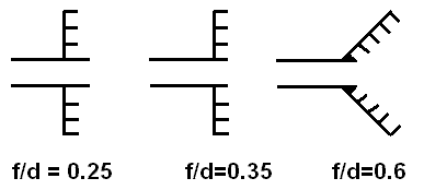
Here is an approximate  diagram explaining scalar rings. If you want to do the job properly for an offset dish with f/d=0.6 or f/d=0.8 you really need a conical horn feed.
...
For an f/d=0.6 offset dish, if you don't have a conical horn but have a feed comprising a circular waveguide with a disk of moveable rings on the outside then move the rings as far towards the dish as possible, as in the middle diagram. The idea is to concentrate the power into the dish. It will work reasonably well, the dish gain will be extra high and the beamwidth will be extra narrow but sidelobes will be extra high and there will be extra spillover losses to the warm ground. End result = not as good as a horn feed designed to match the dish f/d ratio.

If you need more pictures please explain exactly what it is you don't understand.

Best regards, Eric.
Back to top
« Last Edit: Jun 11th, 2018 at 2:00pm by Admin1 »  
 
IP Logged
 
Ex Member
Ex Member


Reply #4 - Apr 3rd, 2007 at 5:53pm  
Thanks a lot Eric, I understood better what you mean.

On the other hand I have several images of the installation that I`ll apreciate you could see them in order to have some feedback. How can I insert them on here or if better for you I can send them to you by e-mail.
Back to top
 
 
IP Logged
 
Eric Johnston
Senior Member
★★★
Offline


Posts: 2109
Reply #5 - Apr 3rd, 2007 at 9:12pm  
Send all the pictures to me by email and I will add them all here.   eric@satsig.net

Best regards, Eric.
Back to top
 
 
IP Logged
 
Pages: 1