Advertisment: Broadband via satellite
Advertisment: Worldwide satellite services from Ground Control Company

www.satsig.net

Satellite Internet Forum.

Welcome, Guest.        Forum rules.
      Home            Login            Register          
Pages: 1

iDirect Rx Saturation Level

(Read 14188 times)
valdemiro
Member
★★
Offline


Posts: 12
Aug 19th, 2009 at 7:50pm  
I am new on the forum and first I want to say hello to everyone.
I want to know if the saturation level for the infinity is from -5 to -60 dBm as the manual show. The reason is because any stations that we found with levels more than -22 dBm we start to get TDMA lost and burst of errors and the solution is keep the levels less than -28 dBm. It was during the installation and we know what to do now but want to know if someone had the same problem and also if is like iDirect manual says what is causing me the problem.

Thanks
Back to top
 
 
IP Logged
 
Ex Member
Ex Member


Reply #1 - Aug 19th, 2009 at 8:50pm  
When you say "saturation"...are you speaking to Rx_power on the line cards and remotes? If so, I believe the optimum value you are looking for is approx -36dBM (+/- 5 dB is my rule of thumb).

Back to top
« Last Edit: Aug 20th, 2009 at 12:48am by N/A »  
 
IP Logged
 
Eric Johnston
Senior Member
★★★
Offline


Posts: 2109
Reply #2 - Aug 19th, 2009 at 10:27pm  
Please give us the url of the manual you are referring to so we can read the same information and help you. I don't have a copy relating to infinity.

Best regards, Eric.
Back to top
 
 
IP Logged
 
valdemiro
Member
★★
Offline


Posts: 12
Reply #3 - Aug 20th, 2009 at 5:21pm  
Is in the Manual of the iDirect Infiniti 300:
RF Power Range
Transmit:-35 dBm to +7 dBm
Receive:-65 dBm to +0 dBm composite
and in the trainig of the IOM presentation
'Network Operations, Basic Acquisition & Troubleshooting
is from -65 to -5 dBm.
Back to top
 
 
IP Logged
 
valdemiro
Member
★★
Offline


Posts: 12
Reply #4 - Aug 20th, 2009 at 5:28pm  
Quote:
When you say "saturation"...are you speaking to Rx_power on the line cards and remotes? If so, I believe the optimum value you are looking for is approx -36dBM (+/- 5 dB is my rule of thumb).


I am speaking of the RX power of the remote. Those levels (-36 dBm =/- 5dB is how I have it but like the manual says -5 dBm I want to know if I am doing right and also to teach some one in the future is better to be clear on it.
Back to top
« Last Edit: Aug 20th, 2009 at 8:06pm by Admin1 »  
 
IP Logged
 
Eric Johnston
Senior Member
★★★
Offline


Posts: 2109
Reply #5 - Aug 20th, 2009 at 8:04pm  
Receive level at a remote
The total composite power into the remote L band input socket must not exceed -5 dBm or 0dBm (in above examples) as this would saturate the L band tuner of the modem.  This power comes from the LNB.  The circumstances of excessive power are when the dish is abnormally large (2.4 - 13m diameter) and the satellite is also broadcasting 30 TV carriers, each 27.5MHz wide and intended for 30cm dia dishes, and short LNB cable.   Such high composite power from a satellte can overload the LNB output stages and you need special low gain LNBs for use in large dishes.  To measure the composite power you need an Agilent (HP) Power meter and N type power meter head (diode or thermocouple) or similar.
In a VSAT don't worry about exceeding the max power into the remote.
As far as the lower limit is concerned, e.g. -65 dBm, the problem could arise with excessive length cable loss between the LNB and the modem.  Read the wanted carrier level in the modem software and compare with the specification.  The specification might say something like Desired carrier: min -130+10log(Symbol rate) dBm, max -90+10log(Symbol rate) dBm.    
Alternatively note the receivce C/N or Eb/No readout.  Then add a length of extra coax to the receive cable to add extra loss of say 6 dB.  This should make the level of the wanted signal go down by 6 dB but should make no difference to the C/N or Eb/No, which should stay the same. (You can't use a 6 dB 75ohm attenuator pad to make this test as the DC would burn it out).  If the C/N or Eb/No does goes down you are clearly approaching the noise floor of the modem input itself. You need a shorter LNB cable, lower loss cable, in-line L band amplifier or higher gain LNB.  Remove or redesign any splitters in the LNB cable.  Note that poor connection in the LNB cable results is low DC supply volts to the LNB and increased L band losses, leading to low signal levels.  At commissioning record levels for reference so you can check remotes from time to time to proactively identify trouble before the customers have an outage.

Transmit level at a remote
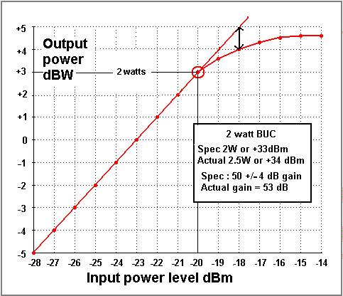
When you set the transmit level at a remote site you must start with a very low level, like -35dBm and increase it only slowly in 1 or 2 dB steps, while watching the CW signal at the hub. You will see it increase in 1 or 2 dB steps.   Plot the values on a graph if you wish.  As you increase the remote power you will find that the BUC starts to go non-linear when the measured level lags 1 dB behind the power settings at the remote then BUC is saturated and you must not go any further.  Record the P-1dB remote transmit power setting in the hub database as the level never to be exceeded in service.  

The uplink power control sytem will reduce the power by several dB to achieve the normal clear sky operating point.

So a 2 watt BUC might normally operate at 0.5 watt output in clear sky and increase during heavy rain to 2 watt (6 dB increase due to UPPC).
It is very important the the UPPC system does not try to increae abve the 2W.  That is why you measure the P-1dB point and then know what modem output power corresponds to the 2W (or whatever is the nominal BUC power).

Ideally, all TDMA bursts arriving at the hub should be at the same level at the line card (+/-1 dB) and all with the same C/N at the hub line card.

If you put too much power into a BUC, even for a moment, you risk damaging the BUC slightly or catastrophically as the output transistors are partially or totally burned out.  Prolonged operation above saturation with the modulation on is bad for the heath of your BUC !

The picture below shows the transfer characteristic of an amplifier with specified power rating of 1.25W.
...
This graph refers to an amplifer with 22dB linear gain.  Typical BUCs have 50 to 60 dB gain and have 1, 2, 3, 4 or 5 watts rated output.

Best regards, Eric.
Back to top
 
 
IP Logged
 
valdemiro
Member
★★
Offline


Posts: 12
Reply #6 - Aug 21st, 2009 at 4:36pm  
Thanks Eric but you confirm too that the input level should be less than -5 dBm and with higher than -24 dBm (that should be ok) I get errors and TDM lost. I do not know if you or someone has stations receiving with more than -22 dBm without issues.
Back to top
 
 
IP Logged
 
Eric Johnston
Senior Member
★★★
Offline


Posts: 2109
Reply #7 - Aug 21st, 2009 at 7:06pm  
I don't understand how you are altering the level.  

If you alter the receive level into the remote modem by swapping in/out various lengths of coax cable in the LNB to modem cable run then that will vary the level of all signals into the remote modem, including the noise floor.  Only if you have exceptionally long cable and thus low levels will you get problems.   The noise floor of the modem itself will have an effect and your outlink C/N and Eb/No will deteriorate.

If you really think that your composite power into the remote modem is exceeding -5 dBm then make the LNB cable much longer.   79 equal power carriers all from the same satellite, each at -24 dBm would make a total of -5 dBm.

If you alter the receive carrier level into the remote modem by adjusting the transmit power at the teleport then you are affecting the C/N and Eb/No directly of that site and all the other sides.  You need to set the nominal level as agreed with your satellite operator.  You pay for a particular power and bandwidth from the satellite.

If increasing the transmit power of the outlink carrier at the teleport causes errors at the remotes then you are likely overloading the BUC or HPA at the teleport hub.  This may also cause errors on the TDMA return links to the teleport due to interference caused to adjacent frequencies either side of the outlink carrier.

The set up and calibration of the transmit power at the teleport should include finding the P-1dB compression point of the hub teleport BUC, particularly if the hub BUC is only a few watts.  In this case connect the output of BUC to a dummy load and measure the output power with a cross-waveguide coupler and Agilent power meter.   If the teleport hub has an HPA it probably has an inbuilt power meter (say 0 - 200 watts).  Use the reading.   Check the output spectrum for spurii and spectral regrowth and intermodulation products if you are transmitting multiple carriers.  I have seen 150W TWTA HPAs that saturate at 10W due to deterioration of the cathode emission.  Record the voltages and currents on the meter every few  months.   Don't test hub HPAs while the big teleport dish is pointed at a satellite.

Best regards, Eric.
Back to top
 
 
IP Logged
 
valdemiro
Member
★★
Offline


Posts: 12
Reply #8 - Sep 30th, 2009 at 10:05pm  
We altered the levels increasing the leng of cable in the RX; we do not play with the TX of the remote. The thing is that only is ok within -24 to -40 dBm and do not know why the manual say -5 dBm.
Probably someone in the forum can share with us their received levels (if is more than -24 dBm) and let us know the performance.
Back to top
 
 
IP Logged
 
Eric Johnston
Senior Member
★★★
Offline


Posts: 2109
Reply #9 - Sep 30th, 2009 at 11:40pm  
The limit of -5 dBm in the manual refers to the applied composite total of all received carriers from the satellite.  The only practical way of measuring (apart from measuring each carrier seperately and adding them all up) is to insert a DC block and provide the LNB power via a side cable.  Then connect a power meter sensor head (of the correct power sensing range or using an attenuator) to the end of the DC isolated L band coax cable. You may need a 75/50 ohm adaptor.  Use an HP Agilent (or similar) power meter to measure the total power - typically using a thermocouple.  Be careful, the test gear is very expensive.

79 equal power carriers all from the same satellite, each at -24 dBm would make a total of -5 dBm.

Overload of the modem receiver tends to occur with very high power satellites or large receive dishes. With both combined you can even overload the LNB output stages, so you need special low gain LNA/LNBs or high power output LNA/LNBs.

Are you receiving from some abnormally high power satellite or group of co-located high power satellites ?

Can you see other high power carriers ? What power and how many of them ?

If the spec says -5 to -60 dBm then your modem might receive a -15dBm carrier if that was one carrier out of 10 similar carriers on the satellite (total power -5dBm).  Alternatively it might receive a -40 dBm carrier, being one out of 3100 similar carriers (total power -5dBm).  I would not advise operating any amplifier or modem at its extreme spec limits.  Always try to set up signal levels through amplifiers working well clear of the noise floor and well below saturation and intermodulation problems.  The problem most commonly occurs in L band and 70 MHz IF distribution systems in large earth stations.

Best regards, Eric.
Back to top
« Last Edit: Oct 1st, 2009 at 8:27am by Eric Johnston »  
 
IP Logged
 
Adrian
Member
★★
Offline


Posts: 17
Reply #10 - Oct 1st, 2009 at 11:09am  
Hello !
I am new in this forum, and if you allow me, I want to ask something about a similar subject  with iDirect Rx Saturation.
I have a vsat station with iDirect netmodem and I notice when I installed the terminal in crowded places like road with many cars I have SCPC errors and TDM lost. I visualised the carriers with spectrum analyser and I notice that are many perturbation due the engine cars.
Do you know a solution to avoid this , except the change the place of installation?
Thanks !
Back to top
 
 
IP Logged
 
Ex Member
Ex Member


Reply #11 - Oct 1st, 2009 at 11:56am  
SCPC errors and TDM loss are certainly indicative of disruption of the downstream carrier.  Either locally or as it is uplinked from the hub.  In your case it is locally.  I will let Eric chime in, but short of relocating that dish, your options may be limited.  What kind of downstream SNR are you seeing to that system (rx snr)?
Back to top
 
 
IP Logged
 
Adrian
Member
★★
Offline


Posts: 17
Reply #12 - Oct 1st, 2009 at 1:42pm  
Downstream carrier to noise is 12-13 dB same as others network's terminals.
On the analyser, the carriers are clean until the perturbation from engine car, appear like spikes in all band over the carrier. (in max hold trace mode analyser).
I have this situation more than one time, in different places.
I check the equipment (RF cable, LNB, BUC, netmodem, ground cable) and I changed one at the time.
I check the right polarisation. (was good)
I think the problem is the near pertubation (in the L band) induced in the RF equipment (LNB). By the way, I use Ku band for transmission.
I know that is a RF problem, but I think I will find an iDirect solution (other than change the type of modulation or similar).
Maybe you have similar situation and solve it somehow until now.

Regards


Back to top
 
 
IP Logged
 
Eric Johnston
Senior Member
★★★
Offline


Posts: 2109
Reply #13 - Oct 1st, 2009 at 1:42pm  
Local interference from car ignition, neon signs, switches, air conditioners, radar etc can cause interference into the LNB.  C band interference from wireless broadband is common.

The problem may be reduced, but not necessarily eliminated, by earth station site shielding.

Interference is also possible due to direct injection of L band (and lower frequency) interference into the cable between the LNB and the modem.  In this case, adjacent cables, cell phones (both base stations and mobiles) and any nearby wireless transmitters are possible sources.  The problem will be aggravated by poor termination of the coax cable screen at the ends or an earth loop. It should be possible, in theory, to eliminate the problem with high quality 100% sheathed cables.

If the antenna base is earthed (often by law) then try a really thick earth cable between the antenna and the indoor rack, routed close alongside the LNB coax.  Earthing the cable sheath near the building entry (often by law) helps to reduce interference and damage if lightning hits.

Best regards, Eric.
Back to top
 
 
IP Logged
 
Adrian
Member
★★
Offline


Posts: 17
Reply #14 - Oct 1st, 2009 at 2:09pm  
I used different types of coax cable, but didn't help. (RG 6, RG 11, Comscope).
More than that I put the netmodem near LNB with the short coaxial cable (no more than 1,5 meter) the result was the same.
Or, I use a different type of netmodem with coax cable no more than 0,5 m. Nothing.
I want specification about one type quality shielded coax cable. 

I will try with the thick cable wrapped on the RF cable like you say. I hope to work.
Thanks Eric


Back to top
 
 
IP Logged
 
Eric Johnston
Senior Member
★★★
Offline


Posts: 2109
Reply #15 - Oct 1st, 2009 at 4:00pm  
Quote:
I will try with the thick cable wrapped on the RF cable like you say. I hope to work.

The thick cable earth idea was only intended as a possible solution to earth loop type interference - which might happen if the antenna base is earthed and the modem is earthed elsewhere.

With the LNB/feed in your hand you can point the feed directly at possible nearby interfering sources while watching the analyser.

Quote:
Or, I use a different type of netmodem with coax cable no more than 0,5 m. Nothing.

Does this mean the different netmodem was not affected by the interference ?  Or was the different netmodem affected much worse by the interference ?. Is the interference getting into the netmodem via the lid joints, via power supply or via the ethernet cable ?

Look at the screen in the cable.  If there is a solid copper or aluminium foil wrapped round and overlapped, that is good.  Mesh wire braid with spaces between the wires is poor.  Note that some cables have plastic foil with aluminium coating (Rf screening) plus wire braiding (for the DC supply).  With moisture, the aluminium coating can turn to a white powder (Aluminium oxide) and become quite useless, while the DC supply happily goes up a widely spaced wire braid wires.

The best screen cable, Andrew Heliax, with solid corrugated copper pipe as the outer screen is too expensive for customer installations.

Best regards, Eric.
Back to top
 
 
IP Logged
 
Adrian
Member
★★
Offline


Posts: 17
Reply #16 - Oct 2nd, 2009 at 7:38am  
1. The antenna and the netmodem are earthed in the same place. The earthed loop was measured and the result was very good.
2. The interfering sources (by direction) came from the streets and appear when the cars moving (some of them).
If I put an obstacle, in the front of the antenna, at the ground level, the perturbation are considerable reduced. But for me, this isn't a solution.
3.The two different netmodem (with different RF equipment, except LNB) are the same behavior related the interfecences.
I think the changing the LNB could be a solution.
4. I will try to get a better cable from Andrew (Thanks).

Best regards, Adrian
Back to top
 
 
IP Logged
 
Eric Johnston
Senior Member
★★★
Offline


Posts: 2109
Reply #17 - Oct 2nd, 2009 at 8:18am  
Quote:
If I put an obstacle, in the front of the antenna, at the ground level, the perturbation are considerable reduced. But for me, this isn't a solution.

I would try to find a location for the antenna so that it is not visible to the road.  As long at it can still see the satellite, the antenna is fine at ground level surrounded by walls or on a flat roof surrounded by low walls.

Quote:
I think the changing the LNB could be a solution.

Worth a try but don't raise your hopes too much. Interference from car ignition is wideband and some of the energy will be at the wanted frequency. If that is causing the errors then changing the LNB will not help.  The total power of the interference may be the problem, in which case the LNB is saturating.  A different LNB with higher output power rating may help.  Invacom VSAT LNBs are particularly well designed. Borrow the LNB if possible so you can take it back if there is no improvement.

Quote:
I will try to get a better cable from Andrew

Not recommended due to high cost and low probability of success in this case.  If pointing the feed (or dish) at the traffic makes things worse then the interference is in Ku band and is getting in via the feed horn, not via the cable sheath.

Best regards, Eric.
Back to top
 
 
IP Logged
 
Adrian
Member
★★
Offline


Posts: 17
Reply #18 - Oct 2nd, 2009 at 8:43am  
Thanks Eric for the advices.
I will try to find an different LNB.

Best regards,
Adrian
Back to top
 
 
IP Logged
 
valdemiro
Member
★★
Offline


Posts: 12
Reply #19 - Oct 2nd, 2009 at 3:46pm  
Adrian,
We had those problems too and if the noise is coming only from the cars you have two solutions as Mr. Eric said, first make a interference study to find another place or and earth station site shielding (Cage) Trying different LNB or cables is not a solution for my based in the problem that you have.
Back to top
 
 
IP Logged
 
Adrian
Member
★★
Offline


Posts: 17
Reply #20 - Oct 5th, 2009 at 11:05am  
Thanks for help,
Best regards,
Adrian
Back to top
 
 
IP Logged
 
Pages: 1