Advertisment: Broadband via satellite
Advertisment: Worldwide satellite services from Ground Control Company

www.satsig.net

Satellite Internet Forum.

Welcome, Guest.        Forum rules.
      Home            Login            Register          
Pages: 1

HX50 commission issues Afghanistan

(Read 6747 times)
revned
Member
★★
Offline


Posts: 3
Nov 15th, 2009 at 8:53am  
Hello all.  I am having issues commissiong our HX50 satellite system. I have spoken to the support staff at Bentley-Walker and still can't figure out the issue, they mentioned they were having interference issues yesterday and to wait until today and still not able to commission the modem.  I'm posting here to see if I can get any other suggestions to help me fix the issue and get me up and running.  I have inputed the configs given to me by Bentley-Walker but the issue seems to be that the transmitter is receiving a TXcode 9 and TXcode 14. The HX50 modem shows we have a Signal strength of 88 percent. I have issued the 'rd' command in telnet to download the new firmwares but it just keeps getting stuck at 'Received RGM'.  I have issued the command several times and it still shows the same thing.  I have also switched the coaxial cables to verify that it is not a cable issue.  My receiving end is fine and does not drop packets, but the transmit side has alot of dropped packets. Could it be a GPS issue? The coordinates we gave Bentley-Walker are of the building the satellite dish sits on and not the actual position of the satellite dish. Is it possible to manually update the modem instead of having it download through the satellite if I could get hold of the latest firmware from BW? Also, in the main screen of the modem gui, i get a diagnostic code of 0000-0000-0400-0041 Below are my config parameters and pictures.

Our Location:
Bagram Airfield, Afghanistan
Satellite: W6 21.6 East
Lat: 34
Long: 69

Config Params
Current Software Image Executing:        Fallback.bin
Creation Date [Release #]:               Oct 17 2008, 14:23:44 [5.8.0.35]
NAT Status:                              Disabled
DHCP Server Status:                      Enabled on Lan1
Firewall Status:                         Disabled
VSAT Zipcode:                            Not Available
=======================================================================
Parameter                                Value entered     Value in use
--------------------------------------   --------------    ------------
VSAT Return Path:                        Inroute           Inroute        
Satellite Longitude in degrees:          21                21            
Satellite Hemisphere:                    East              East          
VSAT Longitude in degrees:               69                69            
VSAT Longitude in minutes:               16                16            
VSAT Longitude Hemisphere:               East              East          
VSAT Latitude in degrees:                34                34            
VSAT Latitude in minutes:                56                56            
VSAT Latitude Hemisphere:                North             North          
Satellite Channel Frequency:             13794 (x 100Khz)  13794 (x 100Khz)
Receive Symbol Rate:                     7000000  Sps      7000000  Sps
Receive Polarization:                    Vertical          Vertical      
Transmit Polarization:                   Horizontal        Horizontal    
LNB 22KHz Switch:                        Off               Off            
DVB Mode:                                DVB-S2-ACM        DVB-S2-ACM    
Frequency Band / Modulation:             Ku / QPSK         Ku / QPSK      
DVB Program Num for User Data:           20500             20500          
DVB Program Num for DNCC Data:           40000             40000          
LAN1 IP Address:                         10.139.19.177     10.139.19.177  
LAN1 Subnet Mask:                        255.255.255.240   255.255.255.240
LAN2 IP Address:                         0.0.0.0           0.0.0.0        
LAN2 Subnet Mask:                        0.0.0.0           0.0.0.0        
IP Gateway IP Address:                   192.168.12.100    192.168.12.100
SDL Control Channel Multicast Address:   224.0.1.6         224.0.1.6      
VSAT Management IP Address:              13.50.2.62        13.50.2.62    


Satellite Statistics Summary
------------------------------------
Network Time: MON JUN 25 18:44:43 2001
------------------------------------

Adapter Main Statistics:
------------------------
Signal Strength.............. 89      Stream Msg-Ackd/Nakd........ 75318/1610
Flags............... 0x00020044       NonStream Msg-Ackd/Nakd..... 314/3
UpTime (d:h:m:s).. 000:02:39:30       Aloha Starts................ 0
WakeUp Aloha Starts.......... 0       Ranging Starts.............. 314
Transport Alarm Bit..... 0x0000       Frames Received............. 890539
Addresses Open............... 8       Frame Errors: CRC/Bad Key... 0/0
Carrier Info....... 021:E:13794       Miscellaneous Problems...... 34198
Rate Code........  256k 1/2 (TC)      No Receive Outroute Lock.... 15
Inroute Group................ 1       No FLL Lock................. 495
Inroute...................... 3       No Network Timing Sync...... 0
IQoS ID...................... 0      


Ranging Reason: No remote-satellite ranging information (new install?)

Inroute Group Selection: Ranged at inroute rate selected by IQoS

Receive Status:  Receiver operational.  (RxCode 5)
Transmit Status: Transmitter adjusting for optimal network timing. (TxCode 9)

[IMG]https://www.satsig.net/bentley-walker/hx/hx-set-up-2zswh9e-s.gif[/IMG]
[IMG]https://www.satsig.net/bentley-walker/hx/hx-set-up-11bkuhw-s.gif[/IMG]
[IMG]https://www.satsig.net/bentley-walker/hx/hx-set-up-vevrc3-s.jpg[/IMG]
[IMG]https://www.satsig.net/bentley-walker/hx/hx-set-up-332osja-s.jpg[/IMG]
[IMG]https://www.satsig.net/bentley-walker/hx/hx-set-up-5z18c5-s.jpg[/IMG]
[IMG]https://www.satsig.net/bentley-walker/hx/hx-set-up-2rwvtow-s.jpg[/IMG]
[IMG]https://www.satsig.net/bentley-walker/hx/hx-set-up-15579mq-s.jpg[/IMG]
Back to top
« Last Edit: May 20th, 2010 at 10:15am by Admin1 »  
 
IP Logged
 
USN - Retired
YaBB Moderator
★★★★★
Offline


Posts: 837
Kentucky (USA)
Reply #1 - Nov 15th, 2009 at 12:09pm  
TX9
TX14
Rate Code 256k 1/2 (TC)
Stream Msg-Ackd/Nakd........ 75318/1610
Each in their own indicate a transmit problem. Cummulatively, they suggest to me a POL angle issue. It's difficult to tell from your photos, but
1. is the "505" on the tapered waveguide adapter (behind the feedhorn) facing up relative to the feedarm?
2. can you confirm that your POL angle is at or near +47.5?
3. have you tried swapping cables? That is, move both ends of the TX cable to the receive side and both ends of the RX cable to the send side?

//greg//
Back to top
« Last Edit: Nov 17th, 2009 at 5:12pm by Admin1 »  

USN (Ret)
 
IP Logged
 
revned
Member
★★
Offline


Posts: 3
Reply #2 - Nov 15th, 2009 at 5:35pm  
Hey Greg,

At first we had the dish rotated around +46 Deg polarization, the tilt at 26 Degrees with the 505 on the horn around the 11-12 Oclock position and the LNB around the 4-5 Oclock position.  That setup, we had 100 percent lock on the satellite meter and an 88 percent signal quality on the modem, but the transmiter was unable to get a lock.  I was able to speak to Bentley-Walker today and they told me to reset the Dish back at 0 Degrees and to set the LNB at around 2 Oclock position.  However, I couldnt get a lock at that angle and the meter's battery died on us and wont let us charge it back again.  Just our luck, talk about Murphy's law.  But anyway, I was able to acquire another satellite meter and just for testing, we decided to rotate the dish again to see if we can get a lock at the current settings.  That was successful but now the dish polarization is at 70 Degrees with the horn 505 at 12-1 oclock and the LNB is around 3-4 Oclock position.  The modem is fully functional now with a 91 percent signal lock, and the transmiter only giving 15 packet loss out of around 8000.  The browsing speed and ping times to websites such as google.com vary from 800-1300ms and downloading varies from 30-40Kbytes.  I guess for tomorrow's project since its around 10PM Afghanistan now, I'll see how we can tweak this further or fix the dish around.

-Denver
Back to top
« Last Edit: Nov 17th, 2009 at 5:12pm by Admin1 »  
 
IP Logged
 
USN - Retired
YaBB Moderator
★★★★★
Offline


Posts: 837
Kentucky (USA)
Reply #3 - Nov 15th, 2009 at 6:58pm  
You may have the tapered feedhorn piece right. But just to make sure, it should be at the 12 o'clock position with respect to the feedarm. In otherwords, if you had the TRIA rotated in its cradle to 0 degrees - and the antenna bracket at 0 degrees azimuth - the 505 should be on top. Straight up.

Now you can set POL with the TRIA cradle, or with the antenna bracket. But NOT with both. If your antenna bracket has the POL angle scale on the back, that's the way to go. Set the TRIA in the cradle to 0, rotate your dish to +47.5 (clockwise from the back). If you don't have the POL scale on the antenna bracket, just set it to vertical. Then rotate the TRIA in its cradle to the +47.5 mark.

//greg//
Back to top
« Last Edit: Nov 17th, 2009 at 5:12pm by Admin1 »  

USN (Ret)
 
IP Logged
 
Eric Johnston
Senior Member
★★★
Offline


Posts: 2109
Reply #4 - Nov 15th, 2009 at 11:16pm  
I agree with Greg.  

The 505 should be directly away from the feed support arm.
Looking at the picture there would appear to be a small error that needs correcting.  

Normally the filter assembly is attached to the tapered tube at one of the 90 deg positions. There are 12 holes in the flange. Looking at the picture you appear to have 30 deg error.

With the LNB sticking out sideways, relative to the feed support arm, that is vertical receive polarisation starting position.

Then for +47.5 deg polarisation adjustment angle turn the entire dish +47.5 deg clockwiase, as viewed facing towards the satellite.

Your receive signal is already good so you are close to getting it right and once you have made the adjustment above I doubt you will see much improvement, if any.  You will however reduce the interference you cause to other people's services.

Regarding your problem it sounds like uplink interference to me. Someone else transmitting up to the same satellite, but wrong frequency, polarisation or transmitting spurious signals or someone on adjacent satellite with too small a dish etc. Get BW and Skylogic to help. It is a real pain when interference is intermittent, as it is from a typical TDMA VSAT uplink.

Best regards, Eric.
Back to top
« Last Edit: Nov 17th, 2009 at 5:13pm by Admin1 »  
 
IP Logged
 
revned
Member
★★
Offline


Posts: 3
Reply #5 - Nov 17th, 2009 at 7:55am  
Hello All. Thanks for suggestions. We are up and running now with a 91 percent signal strength on the modem.  However, the calculations that was given to us off the calculator on this website is different. Below are the calculations given by the azel calc page and the numbers we locked on.

Given Numbers:
Tilt: 25 Degrees
Polarization: 46 Degrees
Azimuth: 242

Numbers locked on Satellite:
Tilt: 25 Degrees
Polarization: 70 Degrees
Azimuth: 199 Degrees

Can this difference sometimes happen?

Here are the stats from the transmitter range page.

Network Time: TUE NOV 17 07:48:31 2009
------------------------------------
State: Not Currently Ranging

Previous Ranging Info [1]
Previous Ranging Info [2]
Previous Ranging Info [3]
Previous Ranging Info [4]
Previous Ranging Info [5]
--------------------------------------------------------------------------------


Successful Rates      | Unsuccessful Rates    | Failed Rates          |
----------------------+-----------------------+-----------------------+
256k Turbo Code 1/2                                                    
256k Turbo Code 2/3                                                    
256k Turbo Code 4/5                                                    
                                                                       
--------------------------------------------------------------------------------


NOC-Sat Delay (AnE).......... 2539559   Remote-Sat Delay (BnD).... 2611626
Remote Distance To Sat (D)... 1042078   SFNP Interval............. 3600000
Ranging ID................... 16        Network Ranged On (L:H:F). 021:E:1379
NOC ID....................... 0         Ranging Record Version.... 1

--------------------------------------------------------------------------------


Rate......................... 256k Turbo Code 1/2    

Available.................... 1         Ranging Reason............. 9
Ranging Sessions Required.... 5         Minimum EsNo............... 28
Target EsNo.................. 48        SwitchUp EsNo.............. 55
Initial Power Setting........ 0         Final Power Setting........ 109
Initial Received EsNo........ 79        Final Received EsNo........ 50
Initial Received C/No........ 620       Final Received C/No........ 591
Outroute SQF................. 92        Outroute C/No.............. 818
Initial Timing Offset........ 581       Final Timing Offset........ 468
Power Control Type........... PWM       Estimated Rate............. No
Coding Type.................. BCH       Inroute Group ID Ranged.... 1

Timestamp.................... NOV 16 14:46:27 (GMT) 2009


Rate......................... 256k Turbo Code 2/3    

Available.................... 1         Ranging Reason............. 0
Ranging Sessions Required.... 0         Minimum EsNo............... 54
Target EsNo.................. 64        SwitchUp EsNo.............. 0
Initial Power Setting........ 623       Final Power Setting........ 40
Initial Received EsNo........ 79        Final Received EsNo........ 64
Initial Received C/No........ 620       Final Received C/No........ 605
Outroute SQF................. 92        Outroute C/No.............. 818
Initial Timing Offset........ 0         Final Timing Offset........ 92
Power Control Type........... PWM       Estimated Rate............. Yes
Coding Type.................. BCH       Inroute Group ID Ranged.... 1

Timestamp.................... NOV 16 14:46:28 (GMT) 2009


Rate......................... 256k Turbo Code 4/5    

Available.................... 1         Ranging Reason............. 0
Ranging Sessions Required.... 0         Minimum EsNo............... 77
Target EsNo.................. 87        SwitchUp EsNo.............. 0
Initial Power Setting........ 623       Final Power Setting........ 0
Initial Received EsNo........ 79        Final Received EsNo........ 79
Initial Received C/No........ 620       Final Received C/No........ 620
Outroute SQF................. 92        Outroute C/No.............. 818
Initial Timing Offset........ 0         Final Timing Offset........ 92
Power Control Type........... PWM       Estimated Rate............. Yes
Coding Type.................. BCH       Inroute Group ID Ranged.... 1

Timestamp.................... NOV 16 14:46:28 (GMT) 2009


-Denver
Back to top
« Last Edit: Nov 17th, 2009 at 5:13pm by Admin1 »  
 
IP Logged
 
Eric Johnston
Senior Member
★★★
Offline


Posts: 2109
Reply #6 - Nov 17th, 2009 at 10:33am  
I am pleased to hear you have it working OK. Well done.

Quote:
Given Numbers:
Tilt: 25 Degrees
Polarization: 46 Degrees
Azimuth: 242

Numbers locked on Satellite:
Tilt: 25 Degrees
Polarization: 70 Degrees
Azimuth: 199 Degrees

Can this difference sometimes happen?


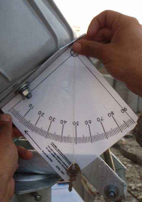
The beam elevation angle (tilt) is the slope of the large circular polarisation scale plate behind the dish. You may apply an inclinometer to the side of this scale plate.
The image below shows the beam elevation angle set to 48 deg.
...
The metal plate behind the dish is at right angles to the beam direction.
You can make your own inclinometer like this by printing out page: How to make inclinometer

I would have expected the final polarisation to be about 50 deg, based on 46.7 calculated plus a possible 3.5 deg Eutelsat satellite offset. This assumes the 505 directly away from the feed support arm and the LNB arm was sticking out sideways initially (for vertical name receive polarisation), when the feed support arm was at the bottom central position.  Adjusted polarisations do vary from the calculation and this is why the hub usually asks you to make an adjustment while they look at your cross-pol signal on their spectrum analyser.  I can't explain a large difference of 20 deg.

My calculated magnetic compass azimuth angle is based on calculation plus an approximation of the earth's magnetic field.  Errors are normally under 5 deg.  Local compass measurments may also be in error due to iron in buildings and structures plus local magnetic anomalies depending on the geology.  The dish pointing maps (eg: dish pointing afghanistan) now include a blue line showing the azimuth direction.  This is helpful as the blue line may be related to the direction of the sides of your roof, building, road, runway (210 magnetic for Bagram) or whatever landmark may be visible in the aerial photo.  I can't explain a large difference of 40 deg.

Best regards, Eric.
Back to top
« Last Edit: Nov 17th, 2009 at 5:16pm by Admin1 »  
 
IP Logged
 
Pages: 1