To avoid distorting the output signal, a BUC must be operated in the linear portion of its input/output characteristic. In the linear part of the range the output signal goes up or down by 1dB for each 1 dB change in the input level.
On a safe frequency, put the remote router into CW transmit mode and observe the BUC output signal on a spectrum analyser.
Now vary the router transmit power in 1 dB steps, each time measuring the BUC output level. As you increase the router transmit power you will reach a point where the step increase in the measured BUC output level is less than 1 dB. The BUC is now going into compression and the signal becoming distorted. Go back down by 1 dB and record the router transmit power. iDirect say to use this value as the "- 1 dB compression point".
Every remote will have a different setting, largely dependent on cable length. Always start with low level router transmit power, especially at any site where the cable length may be short.
In service, the NMS will dynamically vary the remote router transmit power in order to keep the burst signals into the hub at the correct level during rain etc. The hub NMS uses the recorded "-1dB compression point" as the maximum it is ever allowed to tell the remote to use.
If, during testing, you observe that the output power hardly varies with a 1 dB change on the input you have the BUC seriously overdriven. The output signal will be badly distorted and the BUC may be damaged.
Immediately reduce the input level by 10 dB or so and then cautiously re-start the 1 dB step changes.iDirect documentation says...
"The 1 dB Compression Point test is performed with the same CW setup used during the previous cross polarization test. This test establishes the point at which the Satellite Router’s transmit power saturates the BUC.
1. While still in iSite Cross Polarization dialog box and the Network Operator is watching the CW, increase the transmit power of the carrier in the Adjust Transmit Power drop-down box by 1 dBm increments
WARNING The operator should see the CW increase in power by approximately 1 dB. If the power does not increase, then the BUC may already be saturated. Although this scenario is unusual, it can occur.2. If power does not increase, decrease the power by 1 dBm until the operator sees the CW decrease by 1 dB.
NOTE The last point at which the CW changes by 1 dB is the 1 dB compression point.
3. Record the TX power value. This will be used as the maximum power for this remote in the NMS.
4. Click the Stop button to turn off the CW carrier and exit the iSite application.
The 1 dB compression point has now been established."
----
Note for the purist only ...
The expression "-1dB
gain compression point" refers to the input/output levels of a BUC at which its
gain is 1 dB lower than it would have been if it had remained linear. This is the definition used by BUC manufacturers, whose specifications generally quote a rated output power at the -1dB gain compression point. To measure this accurately terminate the BUC with a
calibrated cross-guide coupler and
dummy load and plot the input/output graph using a precision, calibrated,
microwave power meter. Extend the linear line upwards and when the actual output falls 1 dB below the extended line that is the -1dB gain compression point. Some distortion will be occuring at this point and normal operation is best kept backed off a dB or so below this particularly if you operate 8-PSK or 16QAM modulation. Multicarrier operation requires much greater back off to reduce intermodulation products.
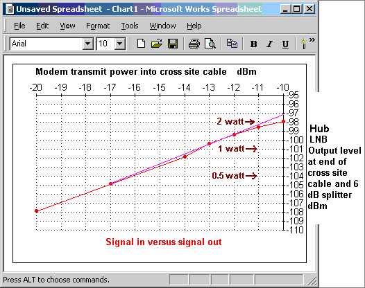
The image below shows the input/output transfer characteristic for a BUC with 2W output at the -1dB gain compression point. Note the 1 dB vertical gap between -97dBm and -98dBm on the right hand side between the extended, straight pink, linear gain line and the actual measured red power curve.

During the last modem power step increment from -11dBm to -10dBm the output power only went up by 0.5 dB. This is now non-linear and starting to distort the output signal.
Best regards, Eric.


