Advertisment: Broadband via satellite
Advertisment: Worldwide satellite services from Ground Control Company

www.satsig.net

Satellite Internet Forum.

Welcome, Guest.        Forum rules.
      Home            Login            Register          
Pages: 1

Help on installing Beacon Receiver and ACU

(Read 15671 times)
kenshin03
Senior Member
★★★
Offline


Posts: 61
Jan 11th, 2011 at 2:33am  
Sir we are installing ASC300LW beacon receiver and VERTEX  7200 ACU on our antenna  system. The ACU is installed already but we are controlling the antenna manually. We wanted to integrate our newly acquired beacon receiver to the ACU to auto track our satellite. No one in the office is experienced on installing this. Am I correct that we have to set the ACU on step tracking mode?
Back to top
 
 
IP Logged
 
Eric Johnston
Senior Member
★★★
Offline


Posts: 2109
Reply #1 - Jan 11th, 2011 at 9:13am  
Read the manual.  This may help: https://www.gdsatcom.com/Controls/Supplemental_Info/7200acs/CG1190C.pdf

Regarding mode of operation I quote
"The 7200 offers a number of operational modes including manual jog control, several programmed positioning modes, "conventional" steptrack, and the revolutionary Orbit Prediction Track (OPT) mode. OPT provides tracking performance approaching that of monopulse control systems by combining efficient steptrack operation with advanced orbital propagation algorithms to produce a state-of-the-art, predictive tracking method. With OPT, the 7200 provides highly accurate tracking with minimal initial data approximately 1.25 hours for initial model development)."

The predictive step track mode (OPT) sounds good to me.

Do make sure that beacon receiver gives out a linear signal and that the controller is set to the same scale (dB/volt). You may need a fixed attenuator on the beacon receiver input.

If it all works well that is fine.  If not it may take several weeks to get it configured correctly.

Some suggestions:
Have more than one person read the manual several times and discuss.
Follow instructions about set up and calibration.
Check that the jog commands actually move the wanted axis and in the expected direction. Look and watch.
Check that the encoder readouts go in the correct direction.
Write down the pointing angles and normal beacon level on a notice next to the controller.
Mark the physical scales at the axes.
Have handles available for manual control.
Set the software limit stops.
Wear a hard hat when outside. Unused, loose washers, rivets or nuts etc may fall down when the antenna moves.
The antenna must be free to move without crushing ladders, breaking waveguides, hot air ducts, power cables etc. Listen for unusual sounds from the motors/gearboxes and use the emergency stop button as required.

Best regards, Eric.
Back to top
 
 
IP Logged
 
kenshin03
Senior Member
★★★
Offline


Posts: 61
Reply #2 - Jan 11th, 2011 at 9:49am  
Sir I started configuring the beacon receiver what frequency is it requiring? I taught it needed the L-Band frequency but when I input our L-Band frequency it does not lock the signal.
Back to top
 
 
IP Logged
 
Eric Johnston
Senior Member
★★★
Offline


Posts: 2109
Reply #3 - Jan 11th, 2011 at 11:27am  
Start with the satellite downlink tracking beacon frequency. See example satellite beacon frequencies.  Tell us here what is yours so I can add it to the list.  Ask the satellite operator if not known. A linear polarisation beacon is useful if you have a circular polarisation system and vice versa, since it will be there all the time regardless of polarisation selection or adjustment.   A PLL type LNB will stop the beacon frequency drifting too far.

Subtract the LNB local oscillator frequency.  Tune your spectrum analyser and beacon receiver to the L band beacon frequency. You should see a CW carrier which will have a very high C/N when you use a narrow resolution bandwidth. There may be telemetry and ranging sidebands as well.

Make sure that the beacon receiver readouts match up with the spectrum analyser over a range of 20 dB down from the peak.  The scale must be linear. Measure the beacon level with the analyser and check that this fits well with the specification input range of the beacon reciver. Put a fixed attenuator if necessary or connect the beacon receiver to a suitable level port in your receive L band IF distribution system.

Best regards, Eric.
Back to top
« Last Edit: Jan 11th, 2011 at 3:46pm by Admin1 »  
 
IP Logged
 
kenshin03
Senior Member
★★★
Offline


Posts: 61
Reply #4 - Jan 12th, 2011 at 12:50am  
Sir I was able to lock the signal but I'm having a low DC voltage even my attenuation level is set to 0dB. My reading is only 5.4VDC. What does this imply?
Back to top
« Last Edit: Jan 12th, 2011 at 2:09am by kenshin03 »  
 
IP Logged
 
USN - Retired
YaBB Moderator
★★★★★
Offline


Posts: 837
Kentucky (USA)
Reply #5 - Jan 12th, 2011 at 4:09am  
One possibility is that you've locked on a beacon side lobe. Drop off and re-access, this time looking for a stronger beacon.

//greg//
Back to top
 

USN (Ret)
 
IP Logged
 
kenshin03
Senior Member
★★★
Offline


Posts: 61
Reply #6 - Jan 12th, 2011 at 6:39am  
Thankyou sir! I'll try to retrack our antenna.
Back to top
 
 
IP Logged
 
Eric Johnston
Senior Member
★★★
Offline


Posts: 2109
Reply #7 - Jan 12th, 2011 at 10:49am  
Possibly peaked up on first sidelobe ring ?:
If you are peaked on the first sidelobe, drive the antenna up/down and left/right and plot the pattern in zero span with say 60 sec sweep time.

If you ever see patterns that suggest the antenna has two approximately equal peaks then go to the mid way position (where you may see a low hollow or hump) and drive along the other axis. This problem occurs when you are peaked up on the first sidelobe ring in any of the four 45 deg quadrant positions, up/left, up/right, down/right, down/left. Whatever way you go you will find two equal maximums, both are the first sidelobe ring and you miss the main beam completely.
 
ASC300–LW Beacon Receiver:
Ref: ASC300–LW Beacon Receiver data sheet

Input Frequency ........ 930 MHz to 2300 MHz
Pre-detection Bandwidth. 50 kHz
Input Level ............-90 dBm, min.; -30 dBm max.
Frequency Tuning ....... 10 kHz Steps
AFC (Note 1)........... +23kHz
Tracking Gradient ...... 0.5 V/dB
Tracking Response ...... 0 to +10 VDC for for a 20 dB input level change

Try to arrange levels so you get a normal maximum in the range 5 to 9 volts (10 to 18 dB at 0.5V per dB). This will allow a useful range downwards (10 to 18 dB), during fades. If the beacon level is too low try connecting the receiver to a splitter port nearer to the LNB. Using an L band inline amp and an associated power supply decreases reliability and is best avoided.  5.4VDC will work fine, but it would just be nice to have it up by about 6 dB to 8.4V, preferably with the input attenuator set to some mid range value, away from zero.

Since the AFC only works over +23 kHz you must have a high stability PLL type LNB with adequate accuracy, unless you have the Note 1 option which allows up to +/-100 kHz in frequency sweep track mode. Tune the beacon receiver to the centre CW carrier if the beacon has lower level modulated telemetry/ranging sidebands either side.

Best regards, Eric.
Back to top
 
 
IP Logged
 
kenshin03
Senior Member
★★★
Offline


Posts: 61
Reply #8 - Jan 13th, 2011 at 12:49am  
ok sir I will return to you as soon we have some improvements. Thanks
Back to top
 
 
IP Logged
 
kenshin03
Senior Member
★★★
Offline


Posts: 61
Reply #9 - Jan 21st, 2011 at 5:16am  
Sir we already installed the beacon receiver and ACU but the problem is we were having an unstable output on beacon receiver causing the ACU to track even we are on peak. Do you think the problem is on the satellite?
Back to top
 
 
IP Logged
 
Eric Johnston
Senior Member
★★★
Offline


Posts: 2109
Reply #10 - Jan 21st, 2011 at 10:57am  
I'm not sure what you mean by beacon instability.

If the level gradually declines over say 10 minutes and then is increased to a higher level following a step track peak up sequence then that is normal. During the step track peak up sequence there will be several step changes in the beacon level as the controller explores small movements in different pointing directions.

During rain the beacon level will vary.  If your intelligent step track has had enough time to learn the daily orbit movement then then the tracking may go to orbit prediction mode during the rain fade.

It is most unlikely that the satellite beacon itself is varying in level - unless you are using a "beacon" that is actually an uplink CW carrier from another earth station.

Monitor the beacon level with a spectrum analyser. Note that if the frequency drifts due to LNB LO temperature and you are using a narrow filter bandwidth this will cause the level to drop. Be alert to this possibility; it applies to both beacon receivers and spectrum analyers.

If you are operating at low elevation angle (under 10 deg at Ku band or under 5 deg at C band) your signals will vary significantly in level due to scintillation.  This involves both upwards and downwards level variations due to refraction effects in the atmosphere. It is the same phenomenon as the twinkling of a star near the horizon. Scintillation occurs for long periods of many hours. In humid conditions scintillation may be observed, to a lesser degree at higher elevation angles, up to 30 deg elevation.

beacon
This graph shows +/-3 dB variation in beacon level at Ku band over one hour at 5.4 deg elevation. Operation of Ku band above 10 deg elevation is recommended.

Faults can cause beacon level variation. Consider loose connectors, DC supply voltages, interference, antenna or subreflector moving in the wind, birds/insects on/in the feed etc.

Best regards, Eric.
Back to top
« Last Edit: Jan 21st, 2011 at 1:24pm by Eric Johnston »  
 
IP Logged
 
kenshin03
Senior Member
★★★
Offline


Posts: 61
Reply #11 - Jan 21st, 2011 at 11:23pm  
Sir beacon reading is unstable even we are not doing any tracking (automatically or manually). Our antenna is on the standby mode and beacon level changes from 1V to 7V on a 1 day period. Could it possibly be a satellite beacon problem?
Back to top
 
 
IP Logged
 
Eric Johnston
Senior Member
★★★
Offline


Posts: 2109
Reply #12 - Jan 22nd, 2011 at 8:38am  
A 6V change and a scale of 0.5V per dB means that the beacon receiver output shows a change of 12 dB over 24 hour period. Was the change gradual and always in same direction or was it quasi-sinusoidal ?  Plot the level on a graph every hour for a couple of days. Does the level vary with satellite's position in its orbit ?  Does the level vary with your LNB temperature ?

Some ideas to try:

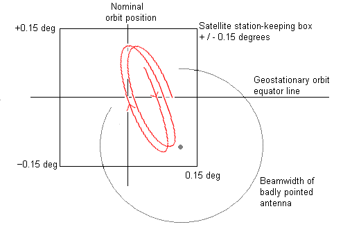
Do the levels of all the carriers on the satellite also change simultaneously over a range of 12 dB ? What variations do you measure with a spectrum analyser ?  If all change the same way then maybe your dish is not pointed at the satellite all of the time, like this:
...
In this example the maximum signal will occur once per day when the satellite approaches close to the beam peak.

Does adjusting the frequency tuning of the beacon receiver make any difference ? In which case maybe the LNB LO is drifting with temperature. Do you have a PLL LNB, preferably with external 10 MHz reference ?

Does manually repeaking the pointing of the dish every hour make any difference ?  The main beam of the antenna has a pointed shape with steep sides and rounded top.  If your dish is fixed, the satellite will move about across the beam pattern and the level will vary, with the pattern approximately repeating every day.  The satellite moves in an ellipse or figure of eight pattern and depending on where is the centre of this pattern relative to your beam centre you will see a variety of quasi-sinusoidal level variations with one or more peaks and troughs over the course of a day.  

Best regards, Eric.
Back to top
« Last Edit: Jan 23rd, 2011 at 3:11pm by Admin1 »  
 
IP Logged
 
kenshin03
Senior Member
★★★
Offline


Posts: 61
Reply #13 - Apr 11th, 2011 at 7:31am  
Sir,

Another question for this, is it normal that the ACU running on OPT control adjust the polarization by up to 10 degrees during auto-tracking?

thanks,

ken
Back to top
 
 
IP Logged
 
Oasis Networks
Senior Member
★★★
Offline


Posts: 232
Reply #14 - Apr 11th, 2011 at 12:31pm  
Hello,

Yes, it is possible. where is the dish located and on which satellite?
Back to top
 

www.oasisnetworks.net - Oasis Networks - Online with you!
IP Logged
 
kenshin03
Senior Member
★★★
Offline


Posts: 61
Reply #15 - Apr 11th, 2011 at 3:36pm  
Sir,

ABS 5 and the dish is in the Philippines,

how is it possible do the adjustment will not affect the opposite polarization?

thanks,

ken
Back to top
 
 
IP Logged
 
Eric Johnston
Senior Member
★★★
Offline


Posts: 2109
Reply #16 - Apr 11th, 2011 at 6:20pm  
To set the polarisation do it manually. Call the satellite NOC and they will ask you to transmit a low level CW carrier on some suitable safe frequency.  They will measure the x-pol level and talk you into the deep null as you rotate the feed in 1 deg (or less steps) around the correct position.   Accuracy of +/- 1 deg is required and the deep null can best be observed on at the satellite NOC teleport spectrum analyser. Record the final position for future reference.

While you are not correctly aligned in polarisation your transmit carrier is interfering with other users of the satellite on the opposite polarisation.

Best regards, Eric.
Back to top
« Last Edit: Apr 11th, 2011 at 7:34pm by Eric Johnston »  
 
IP Logged
 
kenshin03
Senior Member
★★★
Offline


Posts: 61
Reply #17 - Apr 12th, 2011 at 1:15am  
Thankyou sir...

we are doing that thing but the problem is that the ACU is also moving the polarization axis. It automatically adjust the polarization for more than 10 degrees. sir oasis told me that it is possible but my question is, is it normal for the ACU to adjust the polarization axis by that much?

thanks,

ken
Back to top
 
 
IP Logged
 
Eric Johnston
Senior Member
★★★
Offline


Posts: 2109
Reply #18 - Apr 12th, 2011 at 9:35am  
The ACU will probably have a number of satellites pre-configured in its menu.

Each satellite will have a polarisation angle pre-set so when you "go to" a satellite it will set the polarisation up appropriately.

Once you have manually measured the polarisation angle for a particular satellite it should be possible to edit the antenna satellite record to match the manually measured polarisation angle.

The ACU can't 'peak up' on polarisation using the co-pol beacon level as the maximum is much too broad. My guess is that the polarisation is set from a manual data entry or "save current satellite" command.

Best regards, Eric.
Back to top
 
 
IP Logged
 
kenshin03
Senior Member
★★★
Offline


Posts: 61
Reply #19 - May 9th, 2011 at 8:30am  
Sir

We encountered new problem on the system, we lose track on satellite when its raining. Is there a general settings for ACUs to adjust to prevent it from happening?

I can say that the cause of lose of signal is antenna misalignment and not because of rain attenuation. The reason is when we adjust the antenna manually we were able to regain the signal. And please note that the voltage of the beacon receiver drops to 2V which is way below on our 5.8 (-3 dB point).

thanks,

ken
Back to top
 
 
IP Logged
 
USN - Retired
YaBB Moderator
★★★★★
Offline


Posts: 837
Kentucky (USA)
Reply #20 - May 9th, 2011 at 10:51am  
If you have a spare beacon receiver with which to compare, it would help isolate the issue to either the receiver or the rain.

I say that because I've controlled large terminals (up to 18m) in the Philippines myself, and even they'd lose auto-track regularly during rainy season. It was common practice to set the beacon alarm several dB above threshold so that we knew to run over to the console and start manually tracking until the rain passed. Sometimes the rain would completely attenuate the signal, despite our best efforts at manual tracking. When that happened, we just locked the brakes and waited it out. Once that particular cloudburst diminished enough to re-acquire, we'd flip back to auto-track and go about our business.

//greg//
Back to top
 

USN (Ret)
 
IP Logged
 
kenshin03
Senior Member
★★★
Offline


Posts: 61
Reply #21 - May 9th, 2011 at 11:11am  
Thankyou sir greg that will be a big help to us. Then we will just set to manual this time then return to auto track when the weather became good.

thanks,
ken

Back to top
 
 
IP Logged
 
Jurehb
Member
★★
Offline


Posts: 1
Reply #22 - Jul 18th, 2022 at 9:35am  
I would need some advice:
We have tracking 9m ESA with which we are experiencing strange behavior. Antenna is running on step-track mode and  beacon is varying for 3dB.  (graph attached). Antenna is pointed to HotBird satellite. When this antenna was pointed to EUT7W there was only 0.5dB +/- on beacon level.
When antenna is in -3 it is impossible to align it manually to get better results.
Back to top
 

Beacon_signal.jpg (52 KB | 94 )
Beacon_signal.jpg
 
IP Logged
 
Nimrod Kapon
Member
★★
Offline


Posts: 21
Reply #23 - Jul 18th, 2022 at 3:56pm  
Hi,

Look at the interval, they are around 12 hours from peak to peak. Looks like it corresponds to the 8 figure movement of the satellite.

I would start with manually peaking the satellite during the center of box schedule, and then maybe optimize the threshold on the beacon receiver.
Back to top
 

www.oasisnetworks.net
We are your boots on the ground!
GTalk | Skype/VoIP | Facebook  
IP Logged
 
Admin1
YaBB Admin
★★★★★
Offline


Posts: 1192
Reply #24 - Jul 20th, 2022 at 5:55pm  
Agree fully with Nimrod. The smooth quasi-sinusoidal daily variation looks like satellite movement, with tracking not working.

If you are in service beware that a manual verification that you are peaked up on the main beam will involve brief loss of service as you must sweep the antenna across both first side lobes and the main beam, which will be very much larger in the middle. Set to main beam peak and then repeat sideways.

If you see only two similar ‘beam peaks’ you are making a cut through the first sidelobe ring in two places and missing the main beam entirely. Between the two peaks you are seeing the first null. Go there and try a cut at right angles and you will hopefully see the proper cut of two first side lobes with much bigger main beam in the middle.

Another problem with a 9m dish and a very high power satellite like hotbird. The total receive power can overload a high gain LNB. You may need a low gain LNB to get a linear response. If linear the main beam will look the right shape and the main beam will be so many dB higher than the first sidelobes as measured at the antenna installation acceptance pattern tests.
Back to top
« Last Edit: Jul 21st, 2022 at 2:11am by Admin1 »  
WWW  
IP Logged
 
Pages: 1