Advertisment: Broadband via satellite
Advertisment: Worldwide satellite services from Ground Control Company

www.satsig.net

Satellite Internet Forum.

Welcome, Guest.        Forum rules.
      Home            Login            Register          
Pages: 1

HX50-Iraq- TxCode9 & 13

(Read 11825 times)
Ex Member
Ex Member


Feb 26th, 2011 at 10:55am  
Hello.
We took over and moved a previously working setup here in Balad, Iraq. BW Hx50.
We are receiving a signal of 88 (thanks for the inclinometer).
However, we continue to get a Tx Code9 - then after 5 or 10 minutes, it goes to Code 13. BW sent a signal and said the transmit was too weak.

The LBN is P/N 1500287-0001.
Our BUC was stolen the day ofater we moved the system, so we found a replacement (legally). It looks like the one we had, but I do not know if this may be the problem.

I have verified all Manual Commissioning data w/BW.
For Pol, I was instructed not to turn the dish using the large scale on the back, but rather to turn the TIA clockwise to 59.97 (facing the dish).

I have peak the signal using your suggested methods, and have attached pictures to help show my setup & commissioning screen.

Could this be an incompatible Transmit.BUC assembly? Could the feedhorn be the wrong distance from the dish?

The part number on this BUC is not listed as an option on the "Transmitter Radio" portion of the commissioning Page

Any ideas?

Thank you

Jorge

https://www.flickr.com/photos/59998878@N06/
Back to top
 
 
IP Logged
 
Eric Johnston
Senior Member
★★★
Offline


Posts: 2109
Reply #1 - Feb 26th, 2011 at 11:18am  
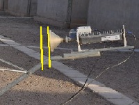
Your feed horn should be about 1.5 to 2 inches further towards the dish.

...
The front rim of your feed horn is opposite the bend in the support arm (wrong position).

...
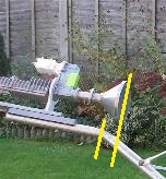
This shows the correct position of the front rim of the feed horn.

Explanation:
You have a 1.2m Prodelin dish intended to be used with a mode-matched feed system.
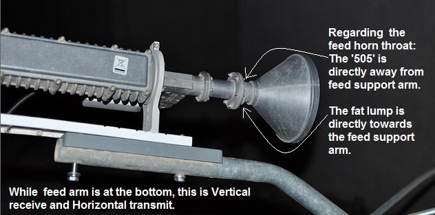
The mode-matched feed system has a special horn, with 505 on top and a lump underneath the throat. The 505 must always be directly away from the feed arm. There is a tapered spacer tube (about 1.5 to 2 inches long) between the grey OMT and the feed horn flange.  When the mode matched feed is used the polarisation must be set using the large scale behind the dish.

You don't now have the mode matched feed horn and tapered coupler tube, so you can set the polarisation using the yoke.  It looks correct. See the picture of your LNB arm here https://www.satsig.net/maps/satellite-dish-pointing-iraq.htm  Select vertical receive and the little picture looks exactly like you have it, as viewed standing behind the dish and facing forwards over the top towards the satellite in the sky.

Best regards, Eric.
Back to top
« Last Edit: Apr 4th, 2011 at 8:48am by Admin1 »  
 
IP Logged
 
USN - Retired
YaBB Moderator
★★★★★
Offline


Posts: 837
Kentucky (USA)
Reply #2 - Feb 26th, 2011 at 12:36pm  
[quote author=jorgelr1 link=1298717720/0#0 date=1298717720]
The LBN is P/N 1500287-0001.
Our BUC was stolen the day ofater we moved the system, so we found a replacement (legally). It looks like the one we had, but I do not know if this may be the problem.
[/quote]Let's get some terminology straight first. You said the "BUC was stolen"  but you list the LNB part number. BUC is an acronym for Block Up Converter, which is the component of that assembly that does the transmitting. It's the long cylindrical piece with the cooling fins. LNB is an abbreviated acronym for Low Noise Block down converter, which is the component that does the receiving.

The entire assembly is called a TRIA: Transmit/Receive Integrated Assembly. From front to rear, the TRIA is comprised of
1. Feedhorn
2. feedhorn coupler (the throat, or "spacer" that Eric mentioned)
3. OMT/filter (Ortho-Mode Transducer, the dull gray thing stamped 1500286 in your photo)
4. LNB (small white box)
5. BUC (transmitter)

So what I'm building up to here is to determine specifically what component or components were stolen/replaced. And the reason that's important is because the 1 watt transmitter and the 2 watt transmitter use the same housing. At a glance, the only way to tell the difference is a piece of green tape, and/or the part number decal. Green tape; 2 watt. No tape; 1 watt. The decal is usually stuck between a pair of fins, and thus rather difficult to read. And in your photo, I don't see any green tape.

You are possibly missing the feedhorn coupler, but not all TRIAs are equipped with one. So I'm unsure how that affects RF output. This rather lengthy explanation is leading to a hypothesis that your substitute hardware may include a 1 watt replacement transmitter. Some of these versions had no coupler. A 1 watt transmitter than is another possible explanation for the weak signal reported by your provider.

//greg//
Back to top
 

USN (Ret)
 
IP Logged
 
Ex Member
Ex Member


Reply #3 - Feb 26th, 2011 at 1:09pm  
Thanks for your reply.

Eric: I moved the Feedhorn 2 inches toward the dish. I stiil get Tx code 9, followed by code 13. However, this time the BUC is actually warm (unless I'm imagining it).

Greg: Thanks for the overview. Our entire TIA was stolen.
I found P/N 1032514-0001 stamped on the BUC at the feedhorn end.

V/r,
Jorge
Back to top
 
 
IP Logged
 
USN - Retired
YaBB Moderator
★★★★★
Offline


Posts: 837
Kentucky (USA)
Reply #4 - Feb 26th, 2011 at 1:26pm  
Well, I don't have that part number on my list Jorge. But what I did notice is that the 10325xx series is associated with the one watt ISIS family of TRIAs. I'm wondering if what you have isn't some kinda hybrid TRIA  cobbled together from spare parts. Where did you obtain this replacement unit? My list suggests two watt transmitters are more commonly associated with the 10335xx (ISIS), 10358xx (OSIRIS), 15001xx (ANUBIS), and 10370xx (ANUBIS) series.

Yours bears a similar resemblance to a spare OSIRIS-TG2 out in my shed, but can't get to it at the moment. Bear with me and I'll try to check for some more part numbers later in the day (it's GMT -6 here).

//greg//
Back to top
 

USN (Ret)
 
IP Logged
 
Ex Member
Ex Member


Reply #5 - Feb 26th, 2011 at 2:28pm  
Units are leaving here without being replaced. If they can't sell what they have, they have to throw it out (refridgerators, microwave ovens, TVs, etc..). We got this complete TIA from one such "graveyard".

So if this is indeed a one-watt unit, could it simply be a matter of selecting "1watt" on the commissioning screen? Or are wee looking at 1watt simply not being sufficient?

Thank you..
Back to top
 
 
IP Logged
 
USN - Retired
YaBB Moderator
★★★★★
Offline


Posts: 837
Kentucky (USA)
Reply #6 - Feb 26th, 2011 at 9:13pm  
Quote:
So if this is indeed a one-watt unit, could it simply be a matter of selecting "1watt" on the commissioning screen? Or are wee looking at 1watt simply not being sufficient?

Unfortunately no. When you "tell" the modem which LNB and transmitter it's connected to, you're in effect telling the provider what kind of hardware is on the other end (they can "see" inside your modem). You can tell the modem anything you want, but it won't change the physical capabilities/limitations of whatever it physically connects through. In your part of the world - 1 physical watt is truly insufficient.

But we're not actually  there yet, remember that this is only a supposition on my part. And I unfortunately haven't been to my shed yet. Forgot I had to make a trip to Ft Campbell today. Only just now returned, so I hope you can spare me another 24 hours.

//greg//
Back to top
 

USN (Ret)
 
IP Logged
 
Eric Johnston
Senior Member
★★★
Offline


Posts: 2109
Reply #7 - Feb 26th, 2011 at 9:42pm  
Did moving the feed system towards the dish improve the receive signal quality ?

Have you repeaked the pointing ?  If not, you will need to repeak the pointing. Getting to the exact centre is important as the transmit beam is narrower than the receive beam.

Tell BW about the uncertainty of the type of long grey transmit module. What does it say on the big white lable on its underside?.  If it is a 1W transmitter, they may be able to assign your return link transmissions to a lower symbol rate frequency slot, where 1W will be sufficient.

Meanwhile, I would experiment with selecting 1W instead of 2W on the config screen. Selecting 1W might cause the modem to try transmitting at 128k instead of 256k, for example.

For the record...
LNB P/N 1500287-0001 has a fixed 10 GHz local oscillator.
This type LNB should be amongst those listed in the SBC.cfg file, and thus visible as options in the pull down menu. e.g.

[RxLnbList]
Pure=10.75,9.75
Invacom=10.6,9.75
1500287-0001=10,10
TG_1024572-0001=10,10
TG_1024572-0002=10.75,10.75
TG_1024572-0003=11.3,11.3

The first two LNBs listed are of the switchable type, with two local oscillator frequencies, where the 22kHz tone has a role.
In the case of the remaining four fixed frequency LNBs, the 22kHz tone does not need to be ON.

Best regards, Eric.
Back to top
 
 
IP Logged
 
Ex Member
Ex Member


Reply #8 - Feb 27th, 2011 at 12:43pm  
The bottom of the Tx says "HUghes  CE 0682".
The signal remained at 88 when I moved the feedhorn forward. I did repeak anyway.
My LNB (P/N  1500287-0001) is not listed on the pulldown, but I was instructed by BW to use "TG_1024572-0001".

Unfortunately, I had to leave for a few days, so I can't check the Tx radio pulldown for the P/N I found stamped on the BUC.

Thanks
Back to top
 
 
IP Logged
 
USN - Retired
YaBB Moderator
★★★★★
Offline


Posts: 837
Kentucky (USA)
Reply #9 - Feb 27th, 2011 at 6:55pm  
Sorry to take so long. Except for not seeing any green on yours, the OSIRIS-TG2 in my shed looks like a clean version of yours. It is Hughes part # 1035818-0002. That's from a green label on the white base, and is the part number for the whole TRIA (what you see on the modem's transmitter dropdown list). I have the CE0682 also. I know positively that my transmitter is 2 watts, and the green label on one of its forward fins clearly reads 1035819-0001. There is a green sticker on the OMT/filter (indicating a 2w TRIA), and there is no feedhorn coupler installed (on mine the feedhorn attaches directly to the OMT/filter, just like yours). This is a new unit, I still have the original Hughes shipping container with all identifying labels. That said, mine won't work in the sand.

So I suspect what you may have found in the "dump", is a 1 watt TRIA from somebody's back yard in Kansas -  that was brought/shipped over and subsequently discarded when it was found not to work. It might work here under North American satellite coverage, but I suggest you look around for another TRIA that's configured to work through middle eastern satellites. In cases where there are enough troops sharing the dish to make the monthly payments equitable (usually 10 or more), there are at least two providers over there that will throw in the hardware for free.

//greg//
Back to top
 

USN (Ret)
 
IP Logged
 
Ex Member
Ex Member


Reply #10 - Mar 7th, 2011 at 7:50pm  
Yes! I think we are getting closer to the WWW.
I have a TRIA with the mode-matched feed system.
Now I have 90-91 Rx, and BW says the Tx is fine. However, we can't get past the "waiting for first heartbeat" message.
This is strange because the HX50 got past that message with the old TRIA. The Power light had stopped blinking quickly after a reset through TELNET (a few weeks ago).
SInce then, we reset again and got the right equipment, but she wont stop blinking.
The 'advanced' screen only shows the fallback BIN as 5.8.0.35_PID. Last time, it had a newer one, with this one as fallback.
BW says they are escalating to Hughes.
Any ideas?
Would Vertical Rx and Hoz Tx being wrong have that effect?
Just in case, I took some pics of my setup to be sure I have it right. I'm wondering if the Tx is at vertical right now.

https://www.flickr.com/photos/59998878@N06/

Nothing else has changed in my settings. I have the '505' directly on top, and used the large scale on the back.

Thank you
Jorge

Inserted by forum admin..
...
With the main polarisation scale on the back of the dish rotated so that the feed arm is at the bottom (or top) centre, and with the feed assembled as shown the receive polarisation is true Vertical and transmit polarisation true Horizontal. Having the feed support arm at the bottom is a starting position prior to applying a polarisation adjustment amount.

This page https://www.satsig.net/maps/satellite-dish-pointing-iraq.htm will give you the polarisation adjustment amount for your location and satellite. Typically a number of degrees clockwise (+) as viewed while standing behind the dish and facing forwards towards the dish and the satellite in the sky, is required for a satellite to the west of south. Use the big scale to count along the amount.

With rx=90-91(good receive) and BW saying your transmit signal is good means that your polarisation is at least about right. Any small error in polarisation adjustment amount is NOT the cause of the current symptom of abnormal heartbeat, blinking etc. This is something for the hub to resolve. The power blinking should stop once a current software version is successfully downloaded and activated.
Back to top
« Last Edit: Mar 8th, 2011 at 5:12pm by Admin1 »  
 
IP Logged
 
Gary-BW
Member
★★
Offline


Posts: 12
Reply #11 - Mar 8th, 2011 at 4:54pm  
Good Afternoon,
This post is to confirm that the site is now operational, the issue of TX13 was caused by the feed assembly setup whilst addtional issues (once TX8 was achieved) were related to software corruption.

Best Regards
Back to top
 

Tel: +44 (0) 23 9231 1118  Web: www.bentley-walker.com Email: gary@bentleywalker.com  MSN: gary_del@hotmail.com
WWW | YIM  
IP Logged
 
Pages: 1