Advertisment: Broadband via satellite
Advertisment: Worldwide satellite services from Ground Control Company

www.satsig.net

Satellite Internet Forum.

Welcome, Guest.        Forum rules.
      Home            Login            Register          
Pages: 1

On Satellites and Transponders

(Read 22302 times)
Ex Member
Ex Member


Apr 30th, 2011 at 4:39pm  
I am new to this Forum, and also to Satellites.

I would appreciate if someone could educate me on the foll basic queries :

1) Post #4 in the site : https://www.dishtracking.com/forum/how-recieve-free-air-channel-on-videocon-sate... gives a broad procedure for tuning to 2 Freqs : 10.99 GHz  and 11.49 GHz  in Insat 4B at 93.5 Deg East.

Also, https://www.satsig.net/maps/satellite-dish-pointing-india.htm gives the foll with the Satellite : "93.5 East Insat 4B" :
Dish Elevation = 66.0 ;  Azimuth = 129.5 (Compass) ;  Polarisation = -50.1

I have a simple standalone Magnetic Compass, but nothing fancy about it. So, how can I go about adjusting for the Azimuth angle above ?

After trying out with diff satellites in the above satsig site, it seems to me that |Azimuth| + |Polarisation| ~= 180 Deg. [|-| => Modulus of]
Pl confirm. If yes, why so ? ; some analysis / explanation would be appreciated.


2) On LNB Alignment ; Is USALS Compliance always necessary / preferred ? :

2-a) Case of Same Freq, but Hor and Vert Pol :
https://www.dishtracking.com/forum/videocon-d2h-dth-on-st-88-east-channels-t-609... gives details of 5 Transponders in ST1 at 88 Deg East.
Transponders 4 and 5 differ only in Polarisation - Trpndr 4 is Vert P, whereas Trpndr 5 is Hor P.
If the Freq is the same (= 11.672 GHz), do we need to realign the LNB for Hor and Vert Pol separately ?
If yes to above, how do we exactly align the LNB when we have BOTH Vert as well as Hor Pol at the same Frequency (= 11.672 GHz) ?
In this specific case, we don't need to rotate the Antenna (same Satellite).
I would like to know if there is a small motor in the LNB also for adjusting the LNB Alignment ?
What sort of Cables do we need to control the LNB movement from the DVR / STB ?

2-b) Control Cables for LNB Alignment and Dish Motor On Multiple Satellites :
https://www.scribd.com/doc/49618243/TELE-satellite-0511-eng - P4 / 58 states :
" Further, the position of the LNB has to be adjusted if the azimuth difference between two satellites is too great.
This must be done in order to properly align the LNB with the satellite's Vert / Hor polarization plane. Otherwise horizontal and vertical transponders cannot not be separated correctly."

So, am I to infer that in such cases of tracking Multiple Satellites, we always necessarily need to have a Motor-operated Antenna Dish & LNB Assembly, and special Coax Cables with "inline" connections to the Antenna Motor ? ie, we necessarily need to have "USALS" or "DiSEqC 1.3" compliance always ?

However, if fixed Dish Antennas are used (which is what most homes use ?, excepting the richer ones), how are the adjustments done for different Frequencies / different Satellites / diff Polarisations etc ?


3) On Power to the Dish Motor ; Power to align LNB :
In a motor-operated Dish Antenna, I have 2 trivial queries :

3-a) Do the so called Inline Control Cables also provide Power to operate the Motor ie, there is no separate AC or DC Power Cable needed to operate the Motor, and there is no special PCB Circuit etc ?
In this case, we can have only 2 types of cmds : "rotate clockwise" or "rotate anti-clockwise" ?
Do Dish Motors work on AC or DC ? At what Voltage ? Their usual Wattage ?

3-b) https://www.scribd.com/doc/49618243/TELE-satellite-0511-eng : P4 / 58 states :
"and another cable going from the motor output to the LNB".
Do LNB Motors work on AC or DC ? At what Voltage ? Their usual Wattage ?
What sort of Cables ("going from the Dish Motor") do we need to control the LNB movement ?

********

Would appreciate expert point-wise replies.

Thanks in advance.

-

********

Pl also see my Posting on the foll Titles :

"Dish, LNB, DVR/STB, Signal Meter, Compass etc"
and
"Sat TV, Dish TV, D2H TV ; Sat Internet Diff"

I separated the queries into these 3 separate Thread Titles, so that there will be less Overlap between these sets of queries.

****************
Back to top
 
 
IP Logged
 
Eric Johnston
Senior Member
★★★
Offline


Posts: 2109
Reply #1 - Apr 30th, 2011 at 5:04pm  
Dish pointing

"Azimuth = 129.5 (Compass)"
Refers to the use of magnetic compass. The value is approximate and may be affected by nearby metal objects. Having set the elevation accurately just swing the dish boldly sideways to find the satellite. Azimuth accuracy is not important except for site planning purposes if you have an obstruction near that direction, in which case use the blue azimuth line as a guide if you can see your house on the web page.

Polarisation

Satellite TV Ku band LNBs normally operate in linear polarisation with the two alternatives (vertical and horizontal) selectable using different DC supply voltages. Ku band LNBs for satellite TV also typically have switchable local oscillators (using 22kHz tone) fo suit the lower and upper halves of Ku band.

If you have a fixed dish, initial set up rotation of the LNB is necessary to suit the wanted satellite. Just set the polarisation adjustment angle using the scale at the feed throat.

If you have a motor driven polar mount, set the LNB polarisation to nominal when the dish is aimed due south. That will suit the due south satellite. As you drive the antenna either way along the orbit the polar mount will cause the polarisations to tilt so as to remain parallel to and at right angles to the orbit line. Most satellite are made that way.

It is unusual to be able to adjust the polarisation of the LNB by using remote motor control. For satellite TV, I have only ever heard of this in relation to C band LNBs (linear polarisation) on large dishes with azimuth/elevation type motor drives.

Quote:
After trying out with diff satellites in the above satsig site, it seems to me that |Azimuth| + |Polarisation| ~= 180 Deg. [|-| => Modulus of]
Pl confirm. If yes, why so ? ; some analysis / explanation would be appreciated.

No.
Azimuth is the 0 - 360 bearing angle in the local horizontal plane. North is zero and the angle increases via East.
Polarisation is feed/LNB rotation. Nominal is zero. Positive adjustment amounts are clockwise as viewed facing towards the satellite in the sky.

Motor drive for polar mounts.

This typically involves 2 wires with a DC supply of 12 to 24 volts. The polarity defines the direction of movement. A further 2 wires are connected to a reed relay that operates for each turn of the motor. You need a compatible receiver/antenna controller that supplies the DC power and counts the pulses. A typical receiver/antenna controller may be programmed for many satellites and many carriers on each satellite. It may take a long time to set up.

Whatever you do, check with your supplier that indoor equipment is compatible with the outdoor equipment.
Back to top
« Last Edit: Apr 30th, 2011 at 6:15pm by Eric Johnston »  
 
IP Logged
 
Ex Member
Ex Member


Reply #2 - May 1st, 2011 at 8:15pm  
Thanks Eric Johnston for yr expert replies.

You have covered most of the points, but it seems that you may have missed commenting upon Pt 2-b of my Msg # 1 above ? - spl wrt Inline Cables, "USALS" or "DiSEqC 1.3" compliance, and how to go about for Fixed Dish etc.

************

4) I have got Google Earth (GE) in my PC.
4-a) Could you pl let me know how I can get the Blue-Green Azimuth Line in GE. Are there any settings in GE that I need to tweak ?
4-b) The Image Date in GE (at the Bottom Left) shows an Old Date for most of the points I have surfed using GE, for eg, 1st Jan, 2009. However, in yr smaller-sized Dish Pointing maps (with the Blue-Green Azimuth Line), the image date shows 2011. Could you pl let me know how I can get the Latest Image Data in GE also.

************

5) In https://www.satsig.net/cgi-bin/yabb/YaBB.pl?num=1286329665 I saw a mention of : 4 Polarisation values :
Polarisation : deg -27.66
Polar mount Main : deg 37.82
Polar mount tilt : deg 5.23
Polar mount axis rotation : deg -26.46

But now, in https://www.satsig.net/ssazelm.htm, I can only find 3 values of Pol.
Could you pl clarify how we can obtain the 4th value : Polar mount axis rotation.

To get a hang of these values, I tried the Az-El Calculator for the same Lat / Long Loc, (let's call it say, A) with North Latitude, with 3 diff Satellites.
For this Loc A with North Latitude :
|Azimuth| + |Polarisation| ~= 180 Deg [Ave for 3 Sat values = 179.487 Deg]

Similarly, I tried to compare the Az-El Calculator for the Lat / Long Loc given in the above https://www.satsig.net/cgi-bin/yabb/YaBB.pl?num=1286329665 Thread, (let's call it say, B) with South Latitude, with 2 diff Satellites.
For this Loc B with South Latitude :
|Azimuth| + |Polarisation| ~= 360 Deg [Ave for 2 Sat values = 355.665 Deg]

And for points exactly on the Equator, we will have :
|Azimuth = Exactly 90| + |Polarisation = Exactly -90| = 180 Deg when the site is to the West of the Sat

|Azimuth = Exactly 270| + |Polarisation = Exactly 90| = 360 Deg when the site is to the East of the Sat

I guess, this settles my previous (Pt 1) in Msg 1 - about the sum of the modulus of the 2 angles being 180 Deg - it should be correctly qualified as foll :
It is either 360 Deg exact, or 180 Deg exact, or close to 360 Deg (for S Lat), or very close to 180 Deg (for N Lat).
Do you agree ?

************

6) During the above Calcs, I also observed that :

For the Loc A with North Latitude :
Very Less Variation in Dish Azimuth Betn : Relative to True N and Relative to Mag N
Ave Diff of 3 Sat Readings = 1.4 Deg

For the Loc B with South Latitude :
Wide Variation in Dish Azimuth Betn : Relative to True N and Relative to Mag N
Ave Diff of 2 Sat Readings = 12.785 Deg

So, in general, has it been observed that the variation betn Az True N and Az Mag N is always higher for South Latitudes ?
I would guess so, since I have taken 2 arbitrary values, one with N Lat and one with S Lat, without any bias in choosing the points.
Do you agree ?
If yes, how can the Calc S/w  be tweaked ?
[As explained in Pt 5 above, for N Lat, the modulus sum : |Azimuth| + |Polarisation| is closer to 180 Deg, than the corresponding sum's closeness to 360 Deg for S Lat.]

Further, after the recent Fukushima Quake, there was a mention that the Earth's Magnetic Axis has got altered. How / Has this been factored into ?

************

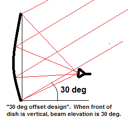
7) In https://www.satsig.net/22-deg-offset-dish.htm, what is the angle of the Base Arm wrt the Diameter Line of the Dish ? Roughly, it seems to be about 80 Deg in the Diagram.
Also, the length of the Base Arm for a given Dish Dia ? ie, I would like to know the ratio of Base Arm Length / Dish Diameter. Is this ratio a certain fixed value ? If yes, how is this ratio value calculated ?

The Red Incident Input Beam Ray hits the Dish slightly above the mid-pt of the Dish.
The Base Arm Length and the above ratio, have a bearing on where this Beam Ray point will be incident on the Dish.

In this Diagram, roughly, I measured the Incident Beam Angle to be about 16 Deg wrt the Horizontal Line in the Diagram.

To put it in other words, as an example, what would be the Base Arm Length / Dish Diameter Ratio, and how would the same Diagram look like, for a 30 Deg Offset Angle Dish ?

************

8 ) I am new in this field, so I would like to understand / get confirmation of the foll :
Feed Arm Point : Pl confirm that this is the same as the (Short) Base Arm, attached to the Dish, and onto which, the Feed Horn Holder is fixed.

Which Pt is the "Feed Throat Point" ?

Cross Polarisation Perf : How is this measured ?

************

PS 1 : As I said earlier, I am new to this Satellite / Transponders / Dish / LNB subject.
So, I wish, that similar to clear replies by you in this Thread, I could also get some little more detailed replies (than the 1 line quick answers from "USN-Retired") to the 2 other Threads :
https://www.satsig.net/cgi-bin/yabb/YaBB.pl?board=point;action=display;num=13041...

https://www.satsig.net/cgi-bin/yabb/YaBB.pl?board=point;action=display;num=13041...

Perhaps, Eric, you may like to add some of yr own comments to those 2 Threads too ! ?
Thanks in advance.

PS 2 : In the "Post a Msg" and "Reply Msg Editor" of this website, how do we get to add Highlights, "Quotes", colors etc ?
Is there any provision to send an attachment file with Calcs or Diagrams etc ?
...

********************

Again, Thanks in advance.
Back to top
 
 
IP Logged
 
Eric Johnston
Senior Member
★★★
Offline


Posts: 2109
Reply #3 - May 1st, 2011 at 10:48pm  
4. Don't use Google Earth; use my page https://www.satsig.net/maps/satellite-dish-pointing-india.htm It shows a blue azimuth line. Regarding "USALS" or "DiSEqC 1.3", try searching Google to find out what these mean.

5. Azimuth and polarisation don't need to be added together. They are output variables that simply need to be applied to the antenna and feed system.

6. The true azimuth bearing can be calculated accurately. The magnetic compass bearing is approximate. The difference between the true and magnetic bearing varies according to your location. The differences are particularly extreme in Canada and to the south of Australia. My calculator does not give magnetic bearings for the polar areas - use the pole star or hand held GPS instead and walk in a straight line. The earth's magnetic field gradually drifts over the years. There are also small fluctuations daily due to solar wind, rather than earthquakes.

7. The geometry of offset dishes varies from one manufacturer to another. The feed horn is usually near the beam edge to minimise obstruction of the beam. Read the manufacturers documentation to find the offset angle. The offset angle normally refers to the beam elevation when the front face of the dish is vertical and the feed arm at the bottom.
...
You must hold the feed in correct position using any rigid structure. You choose the dimensions of the support arms.

8. "Feed Arm Point" and "Feed Throat Point". You can define these how you want.
If you make measurements to the surface of the reflector near where the feed arm is attached note that this point may close to but not actually on the axis of the parabola. The phase centre of the feed is the point where the rays from the feed appear to originate and this point is put at the focus of the parabola. The position of the phase centre varies according to the design of the feed. In feeds with long narrow taper the phase centre is near the aperture. In short feeds with a broad angle taper the phase centre is back down near the throat. The phase centre may move with frequency.

You measure receive cross-pol performance by comparing the co-pol and cross-pol signals. Use a CW beacon, a PLL LNB and measure with an analyser using a narrow resolution bandwidth so as to get a high co-pol C/N.

You may add images to your postings here using this format:
(img)https://www.example.com/imagefilename.jpg(/img)
Use square brackets instead of round brackets. Put the images on a server somewhere.
wxw
Best regards, Eric
Back to top
« Last Edit: May 2nd, 2011 at 9:42am by Admin1 »  
 
IP Logged
 
Ex Member
Ex Member


Reply #4 - May 14th, 2011 at 10:57am  
Thanks Eric Johnston for yr replies dt 1st May 11.

This Msg Sub-Title : More Info required of each Transponder of the Satellite

1) In most of Forums' Disc that I have seen so far, FEC is often mentioned, but I could not see the foll info for each Transponder : (pl see below from (i) onwards - after the info in [...]) :

[ I would like to have the values of the Parameters (i) to (xi) described below atleast for the popular Indian Satellites / Transponders :
-      IntelSat 4B, 93.5 Deg E : Ku Band India
-      IntelSat 4A, 83 Deg E : Ku Band
-      NSS6, 95 Deg E : Indian Beam
-      ST 1, 88 Deg E
]

i) CRrs : Reed Solomon forward Error Correction (FEC) Code Rate eg, 188/204
ii) Any Turbo Coding FEC : e.g. 5/16, 21/44, 3/4, 7/8, 0.95
iii) Modulation Factor (transmission rate bits per symbol) m : eg, BPSK=1, QPSK=2, 8PSK=3, 8QAM =3, 16QAM=4 etc

[In https://www.satsig.net/symbol01.htm, we can see some calculations using the above Parameters.]

Further, I could not see :
iv) the Bandwidth at selected dB values : eg, the BW at the -3.8 dB Points, -10 dB levels etc
v) Adjacent Carrier Interference Allowance on each side : eg, 28 dB ? on each side
For each Satellite Beam, we need to have the Transmit Beam Pattern showing the Main Lobe and the Side Lobes, with dB (below Max Gain) on the Y Axis, vs the distance from the Central Lobe as the X Axis.

vi) Transponder's Full Bandwidth : for eg, is it 27 MHz or 54 MHz, or ?
vii) Has the Transponder's BW been split into 2 equal Half Transponder BWs etc ?
viii) Has SCPC (Single Channel Per Carrier) been employed ? - at what BW etc ?
ix) What is the CNR (Carrier to Noise Ratio) Threshold for a good receipt of signal strength ? - for eg, is it 10 dB (for Analog Transmission ?), and 6 dB (for Digital B/Cast ?) etc ?

Knowledge of these parameters, will help in choosing a proper Dish, and later adjustments, experiments as a hobbyist etc.
[In https://www.apsattv.com/techinfo/predicting-out-of-footprint-coverage.htm, there is some disc on these points for Satellites covering the NZ region.]

[I have already gone through some Transponder (Tps) listed in the lyngsat site for some of the Satellites, for eg, like : https://www.lyngsat.com/in4b.html.]

2) For Sat Internet, we further need to know :
x) Uplink G/T (dBK) {Gain to Noise Temperature ratio Contours}
xi) PFDSat {Uplink Power Flux Density required at the satellite to saturate a transponder}

3) For (Full) HD Channels, in the above Satellites / Transponders, I would like to know the values of the Parameters (i) to (xi) mentioned above.
For eg, the Transponder's Full Bandwidth, and the actual BW employed for Full HD-3D B/Cast Channels in India ; are HD Channels employed on Half Transponder BWs, or on SCPC or - ?

***********

Thanks in advance (TIA) for yr replies.

...
Back to top
 
 
IP Logged
 
USN - Retired
YaBB Moderator
★★★★★
Offline


Posts: 837
Kentucky (USA)
Reply #5 - May 14th, 2011 at 1:26pm  
1. FEC is a function of subscriber modems, it has nothing to do with the transponder itself
2. G/T is a physical characteristic of a given receive system - will vary between/among terminals - and also has nothing to do with the transponder itself.
3. transponder bandwidth varies among satellites. And on many satellites, there are transponders of varying bandwidth. Bandwidth is leased based upon subscriber requirements. If it's not a full transponders worth, the remaining bandwidth is simply leased to someone else.

//greg//
Back to top
 

USN (Ret)
 
IP Logged
 
Admin1
YaBB Admin
★★★★★
Offline


Posts: 1203
Reply #6 - May 14th, 2011 at 2:00pm  
Quote:
2) For Sat Internet, we further need to know :
x) Uplink G/T (dBK) {Gain to Noise Temperature ratio Contours}
xi) PFDSat {Uplink Power Flux Density required at the satellite to saturate a transponder}

Uplink G/T (dBK) relates to the uplink beam gain contours and the satellite receive system noise temperature which much influenced by ground/sea/cloudtop surface (~290K).

The PFDsat varies exactly (in contour step increments) as per the Uplink G/T contours.
The actual value of PFDsat is typically adjustable over a 10 - 20 dB range using on board gain adjustment, which may be on a combination of both beam basis and transponder basis. Transponders may be set low gain so as to maximise the uplink carrier eirp and thus uplink C/N.  Transponders set to high gain minimise the required uplink eirp but degrade the uplink C/N and also degrade the uplink C/Interference (both adjacent satellite and cross-pol). Some transponders may have AGC (automatic gain control) so as to keep the output power constant at maximum, to keep a TV carrier at its full power down, despite rain fading in the teleport uplink.

The general idea is to maximise the transponder capacity by adjusting the transponder gain setting. If you rent an entire transponder you can reasonably expect to have some influence over the gain step setting although consideration must be given to the people operating in the cross-pol transponder.

Best regards, Eric.
Back to top
 
WWW  
IP Logged
 
Ex Member
Ex Member


Reply #7 - May 18th, 2011 at 7:52am  
Thanks to Eric and USN_Retired for describing the meaning of the 2 Parameters (2-x) and (2-xi).

However, I am interested to know the actual current existing values (typical 2011 figures) of these (i) to (xi) Parameters of the 4 Satellites that beam over India, let us say, as Case Studies.
[But, as per USN_Retired's Msg #5, we may have to remove the FEC related parameters from this list of 11 Pars, I guess ?]

If there is / are link(s) where we can get ALL such details (ie, the above Parameters that I have mentioned, and some more Parameters of interest, if any) of individual Satellites / Transponders / Beams etc, that would be great !

If you provide me with such link(s), then, I can dwell into the details to fetch all these parameters for the 4 popular Indian Satellites :
-      InSat 4B, 93.5 Deg E : Ku Band India
-      InSat 4A, 83 Deg E : Ku Band
-      NSS6, 95 Deg E : Indian Beam
-      ST 1, 88 Deg E

TIA & Rgds

PS : It was my Typo Error in Msg # 4 to have typed IntelSat, when I actually intended to refer to InSat ie, InSat 4B and InSat 4A.

...
Back to top
 
 
IP Logged
 
USN - Retired
YaBB Moderator
★★★★★
Offline


Posts: 837
Kentucky (USA)
Reply #8 - May 18th, 2011 at 11:29am  
I can't speak for Eric, but those in my particular satellite sub-specialty don't use the acronym G/T with regard to the orbital platform. Rather, we use the phrase "transponder gain". So when I responded to the G/T question, I instinctively limited my response to earth station terminology. With regard to the orbital platform, we use "transponder gain" rather than G/T. The difference between your terminology and mine may simply be related to which particular variant of the link budget algorithm you're studying.

Transponder gain is a dynamic value, and is under real-time control of the satellite owner. That is, if we even knew the value while typing this response - the value could have been changed by the time you read it. Not that they often change that rapidly, but the potential is there - particularly in transponders with available bandwidth.

Every time a potential customer requests bandwidth, the folks who control the affected satellite perform a link budget analysis. Besides determining operating parameters for the requesting station, the link calculations also consider the transponder gain. If the request for service exceeds the current gain state - and there is available power left to support the new requirement - the satellite owner will then simply increase the gain state.

Understand however, that it's not as simple as just "turning it up". Any gain state change - up OR down - will necessarily impact the link budget of every other customer transiting that transponder. Every other customer transiting that transponder may be notified to make compensatory changes at their respective terminals, in compensation for the new customer requirement.

Long story short, the current gain state of any given transponder - as well as answers to some of your other questions - is information typically limited to the satellite owner and selected satellite control centers. That said, there's nothing stopping you from contacting one or the other - and simply asking for the information. Short of that, it's not information widely disseminated to the general public.

//greg//
Back to top
 

USN (Ret)
 
IP Logged
 
Admin1
YaBB Admin
★★★★★
Offline


Posts: 1203
Reply #9 - May 18th, 2011 at 1:30pm  
For these satellites:
- InSat 4B, 93.5 Deg E : Ku Band India
- InSat 4A, 83 Deg E : Ku Band
- NSS6, 95 Deg E : Indian Beam
- ST 1, 88 Deg E

If you want to do comparitive analysis you need the following:

Uplink G/T and PFDsat contour maps and downlink EIRP contour maps.
Actual transponder operating points, i.e. back off in and back off out.

Transponder gain step settings. Clarify with the satellite operator which gain setting is the reference used for the uplink PFDsat contours.

Only the downlink EIRP contour maps are widely publicised as a marketing tool. Note they assume that the transponder is saturated with single carrier (i.e. zero output back off).

You might also ask for the curve for carrier/intermod versus operating point.

Ask the satellite operators for the parameters. It is not a problem.

If you are proposing doing something extreme ask for details of their earth station requirements in terms of off-axis interference emissions etc. All satellite operators will limit your earth station off-axis emissions to protect adjacent satellites.

Best regards, Eric.
Back to top
« Last Edit: May 19th, 2011 at 5:33am by Admin1 »  
WWW  
IP Logged
 
Pages: 1