Advertisment: Broadband via satellite
Advertisment: Worldwide satellite services from Ground Control Company

www.satsig.net

Satellite Internet Forum.

Welcome, Guest.        Forum rules.
      Home            Login            Register          
Pages: 1

HX50 pointing problem in afghanistan plz help

(Read 31475 times)
afghan-gsm
Member
★★
Offline


Posts: 34
Dec 24th, 2011 at 2:09pm  
hello to all friends and medrators mr eric
I have problem with pointing the dish in w6 21.6 degree
Other information
Receive polarization vertical
Transmit polarization horzontal

Location information
Dish elevation (deg) 31.65
Dish azimuth (deg east relative to megnatic north) 236.84
Polarisation angle (deg) 43.24
Clockwise rotation whilst standing in front of the feed assembly facing the dish
Back to top
« Last Edit: Dec 25th, 2011 at 10:06am by Admin1 »  
 
IP Logged
 
Eric Johnston
Senior Member
★★★
Offline


Posts: 2109
Reply #1 - Dec 24th, 2011 at 2:17pm  
Please describe your LNB and dish.

What is the model number of your LNB ?

Do you have a large, grey coloured, wedge shaped plastic box behind the antenna ?

Best regards, Eric
Back to top
« Last Edit: Dec 25th, 2011 at 10:06am by Admin1 »  
 
IP Logged
 
afghan-gsm
Member
★★
Offline


Posts: 34
Reply #2 - Dec 24th, 2011 at 3:17pm  
thnk you mr eric
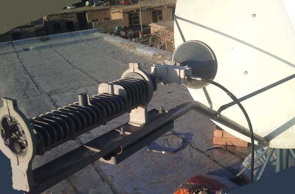
just i have these two pictures if help to to know my lnb module.
dish is 1.2 m
Back to top
« Last Edit: Sep 13th, 2015 at 3:43pm by Admin1 »  
 
IP Logged
 
Eric Johnston
Senior Member
★★★
Offline


Posts: 2109
Reply #3 - Dec 24th, 2011 at 5:27pm  
...
This image above shows Hughes Universal LNB PN LNB 1501882-0002.
The receive polarisation is Horizontal name.  No adjustment amount has yet been applied.


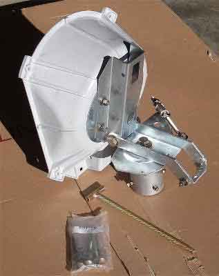
Please say if you have a large, grey coloured, wedge shaped, plastic box behind the antenna, similar to that shown on the left of the image below  ?.
...
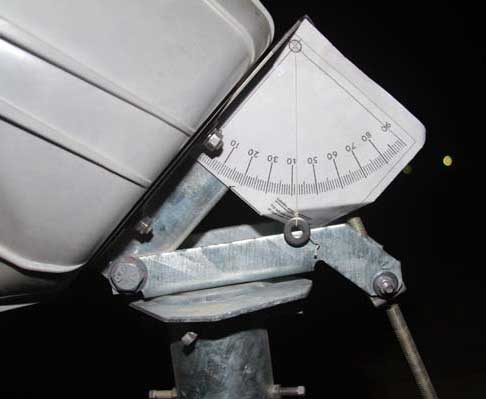
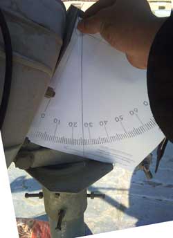
This image shows the elevation angle being set using an inclinometer. Read how to make inclinometer


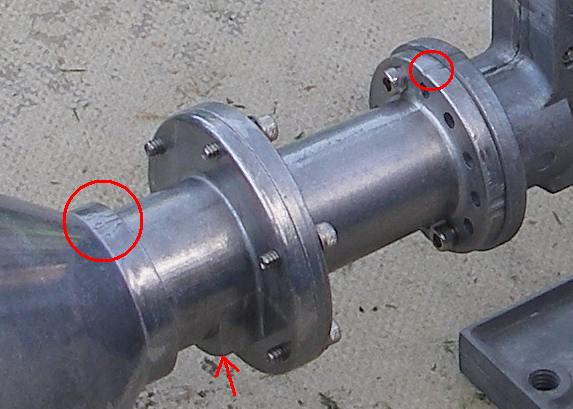
Please look for a tapered grey adaptor tube between the conical feed horn and the LNB module.
...
Does such a grey spacer tube exist ?
The tapered grey adaptor tube has flanges at each end. The smaller flange, with 12 holes, has 2 tick marks on one place and 1 tick mark in another place. The single tick mark must be directly away from the feed support arm tube.  On the throat of the conical horn is a 505 mark.  This 505 mark should also be directly away from the feed support tube. The fat lump underneath must be towards the feed support arm.

Best regards, Eric.
Back to top
« Last Edit: Dec 25th, 2011 at 10:06am by Admin1 »  
 
IP Logged
 
afghan-gsm
Member
★★
Offline


Posts: 34
Reply #4 - Dec 25th, 2011 at 5:52am  
hello to all friends and mr eric
to day i have tried alot the high signall i got a bout 29 ans stuck there \
my lnb detail
HS 10.95-12.75GHz
p/n 1501882-0002
REV.A
S/N J09C025114C1
it is commitsstion pic that i have applied
Back to top
« Last Edit: Sep 13th, 2015 at 3:43pm by Admin1 »  
 
IP Logged
 
Eric Johnston
Senior Member
★★★
Offline


Posts: 2109
Reply #5 - Dec 25th, 2011 at 9:41am  
Signal=29!  Well done. You have found a powerful satellite. It is useful to mark and record this position so you can always get back to this first found satellite.  The other satellites are in a sloping line across the sky. You may be pointed at the wanted satellite if your elevation angle is correct.

The signal scale works in two ranges:   0 to 29 refers to signal power.  You will get readings on all satellites as you pass them. Really powerful satellites will give a reading of 29, which is the maximum value.
The second range goes from 30 to 100. Expect a result in the 90's.  This scale only appears once your receiver has detected the wanted carrier. This means you have the correct satellite, correct polarisation, symbol rate, frequency, LNB type, tone on/off, in the config screen are all correct.

Pointing:   Using https://www.satsig.net/maps/satellite-dish-pointing-afghanistan.htm  I get quite different elevation angle.  I don't know why the figures differ.  Find and check your location on the map and check. What town are you in ?

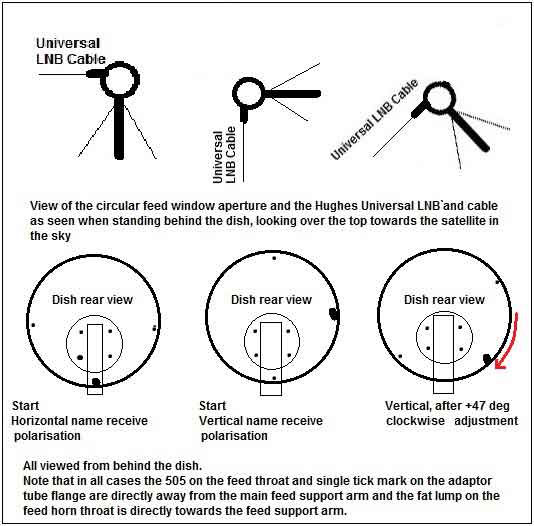
Polarisation:  As per your picture with the feed arm at the bottom of the dish and the Universal LNB cable sticking out at the side. This is Horizontal polarisation name starting position.  You want Vertical name receive polarisation.  If you have a large grey wedge shaped plastic box behind the dish go there and loosen the 4 polarisation bolts and turn the dish anticlockwise by 90 deg (as viewed from behind the dish). You are now at vertical polarisation name starting position. Now adjust the dish by an amount of 47 deg clockwise. Use the scale to count the along the amount of 47.  Ignore the numbers if they go backwards from 90, for example.

Having the wrong polarisation will result in high signal power (a mixture from both polarisations) but the two  signals, from each polarisation, will cause severe interference with each other so there is no hope of receiving anything.  With the polarisation adjusted correctly (+/-1 deg accuracy) the unwanted interfering cross-pol signal will be nulled out and disappear.

Best regards and Happy Christmas, Eric.
Back to top
 
 
IP Logged
 
afghan-gsm
Member
★★
Offline


Posts: 34
Reply #6 - Dec 25th, 2011 at 12:53pm  
hello to all friends and mr eric that helped me alot
friends it is 3 days that i am pointing the dish from 8 am till 5 pm it realy mede me crazzy
still i couldint found the satalite
the only signall cames is 29
i have some qustion
is there any option to factory reset the hx50 mdeom
is there any software to update mdeom frimware
becuse i may upload CBC.cfg file in other place
and this pics are my dish after instalition

one more qustion i have one satalite finder here is the pic
if possible if it can help me and how to use
Back to top
« Last Edit: Sep 13th, 2015 at 3:44pm by Admin1 »  
 
IP Logged
 
Eric Johnston
Senior Member
★★★
Offline


Posts: 2109
Reply #7 - Dec 25th, 2011 at 1:47pm  
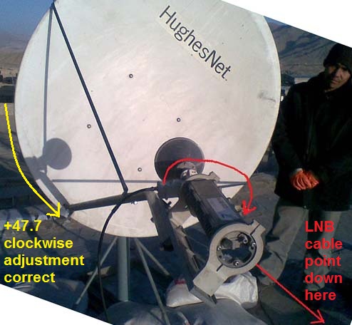
...
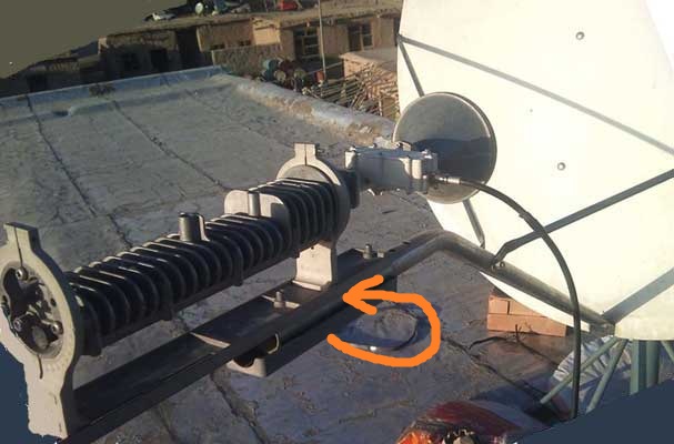
This shows the LNB BUC assembly turned in its yoke - which is not really a good idea as the 505 on the feed throat and single tick mark on the flange are no longer directly away from the feed support arm and the fat lump is no longer towards the feed support arm.

The polarisation orientation is completely wrong. You need Vertical polarisation name, adjusted by +47.7 deg clockwise, as viewed, looking forwards from behind the dish.

...
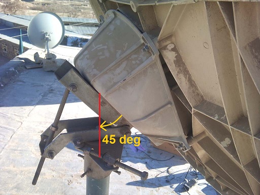
This shows the grey wedge shaped box. the elevation angle is set to about 45 deg. I think the elevation should be 26 deg. You think the elevation should be 31.6 deg.
Set the elevation correct using an inclinometer.
Read how to make inclinometer

Are there 4 bolts and a giant circular polarisation scale on the left face of the grey wedge shaped box ?
If yes then follow instructions at A below.
If no then follow instructions at B below.

The use of a satmeter is similar to the 0 - 29 scale on the screen readout.  The satmeter will indicate at all satellites and to peak up on any. If you set the elevation correct, then swing boldly sideways, you may well find the wanted satellite on the first swing. Even if you get the wrong one, the wanted satellite will certainly be the next one either way along the diagonal sloping orbit line.

Polarisation method A. You have a giant polarisation scale and 4 bolts on the rear of the grey wedge shaped box. It is possible to loosen the four bolts and rotate the entire dish through 360 deg.

With the feed arm at the bottom of the dish and the Universal LNB cable sticking out at the side. This is Horizontal polarisation name starting position.  You want Vertical name.  You have large grey wedge shaped plastic box behind the dish; go there and loosen the 4 polarisation bolts and turn the dish anticlockwise by 90 deg (as viewed from behind the dish). You are now at vertical polarisation name starting position. Now adjust the dish by an amount of 47.7 deg clockwise. Use the scale to count the along the amount of 47.7  Ignore the numbers if they go backwards from 90, for example. The feed support arm will now be on the lower right hand side as viewed from behind the dish, facing forwards towards the satellite in the sky.

Method A is best and in the unlikely event that you have been told the wrong name of your downlink polarisation it is very easy to turn the whole dish 90 deg.  Note that the beam should stay pointed at the satellite even when you turn the dish. In practice you need to retighten the 4 screws and peak up again.

Polarisation method B. The polarisation scale and 4 bolts on the rear of the grey wedge shaped box are missing. You cannot rotate the dish. The feed support arm is always at the bottom of the dish, near to the ground.

Turn the LNB/BUC assembly in its yoke till the Universal LNB cable points upwards. This is a vertical polarisation start position.
Now turn LNB/BUC assembly in its yoke by an amount of 47 deg clockwise, as viewed from behind the dish, facing forwards towards the satellite in the sky.  Your system will probably now work, although the polarisation isolation will be poor.
Undo the 6 screws at the 12 hole flange and reattach with the 505 and single tick mark as near as possible to directly away from the feed support arm and ther fat lump towards the feed support arm.

Best regards, Eric.
Back to top
 
 
IP Logged
 
afghan-gsm
Member
★★
Offline


Posts: 34
Reply #8 - Dec 25th, 2011 at 2:16pm  
really thank you mr eric and sorry to disturb you a lot.
sorry my english is not good i took this info from the site that you gives the link it is my exact location and if possible show in a picture how i should polarize my lnb and other

Satellite antenna dish aiming angle / pointing calculator for Afghanistan, with map

Lat    = 33 degrees,   8 minutes   North
Long = 67 degrees,   26 minutes   East

If you want to point a satellite TV dish at the Satellite at = 21.5 East orbit longitude

Beam elevation= 28.0, Azimuth= 239.1 (magnetic compass), Polarisation= 47.7
Back to top
 
 
IP Logged
 
Eric Johnston
Senior Member
★★★
Offline


Posts: 2109
Reply #9 - Dec 25th, 2011 at 2:21pm  
OK set the elevation to 28 deg using an inclinometer. Then swing the dish boldly sideways to find the satellite.  Obviously, set the polarisation correct first.

Tell your service provider hub your correct location and modify the location on the config screen.  Having wrong location will not affect your ability to receive from the satellite but it will prevent your transmit side from transmitting at the correct time so as not to interfere with other site uplink bursts.

Best regards, Eric.
Back to top
 
 
IP Logged
 
afghan-gsm
Member
★★
Offline


Posts: 34
Reply #10 - Dec 25th, 2011 at 4:13pm  
thank you mr eric if possible plz tell me how to set polarization to 47.7 degree i mean  where it shows  i should rotate the lnb
Back to top
 
 
IP Logged
 
Admin1
YaBB Admin
★★★★★
Offline


Posts: 1206
Reply #11 - Dec 25th, 2011 at 5:30pm  
Do you have 4 nuts visible on the rear face of the wedge shaped plastic box behind the dish with an associated circular metal disk?.
...
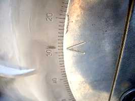
On the rear of the wedge shaped box there may be a giant 360 deg circular polarisation scale. Can you see this scale ?  Can you see V shaped marks either side on the metal disk, similar to that shown below?.
...
Can you loosen the 4 bolts slightly and then rotate the entire dish?

If your answer to all the above is Yes, then follow these instructions:

With the feed arm at the bottom of the dish (near the ground) and the Universal LNB cable sticking out exactly sideways. This is Horizontal receive polarisation name starting position.

You want Vertical name starting position.  You have large grey wedge shaped plastic box behind the dish; go there and slightly loosen the 4 polarisation bolts and turn the whole dish anticlockwise by 90 deg (as viewed from behind the dish). Get someone to help you hold and turn the dish.  You are now at Vertical polarisation name starting position.  If you have a look round the side of the dish you will see the BUC/LNB out on the right hand side with the LNB cable connector pointing exactly up/downwards.

Now adjust the dish by an amount of 47.7 deg clockwise. Use the scale to count the along the amount of 47.7
Ignore the 0, 90, 180 numbers if they go backwards from 90 or whatever. Adjusting by an amount of 47.7 deg clockwise is what matters.  The main feed support arm will now be on the lower right hand side as viewed from behind the dish, facing forwards towards the satellite in the sky.

Retighten the 4 polarisation plate nuts. The beam should  still be pointed at the satellite, but in reality will need peaking up slightly!

Best regards, Eric.
Back to top
« Last Edit: Dec 25th, 2011 at 7:34pm by Admin1 »  
WWW  
IP Logged
 
afghan-gsm
Member
★★
Offline


Posts: 34
Reply #12 - Dec 26th, 2011 at 7:55am  
hello to all and mr eric
to day also i have tryed alot and no luck
it is the picture of elivation i used
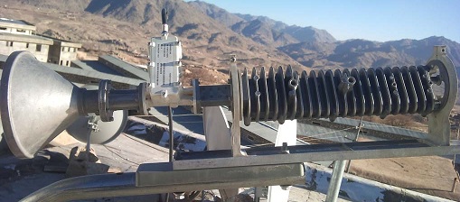
and it is the lnb pic i took
plz if any can help how to fix this head eoch
Back to top
« Last Edit: Sep 13th, 2015 at 3:44pm by Admin1 »  
 
IP Logged
 
Admin1
YaBB Admin
★★★★★
Offline


Posts: 1206
Reply #13 - Dec 26th, 2011 at 9:49am  
...
This shows the beam elevation set to 26 deg. You need to adjust it a further 2 deg up to get to 28 deg elevation.

I can't see your feed image file.
This may help:
...

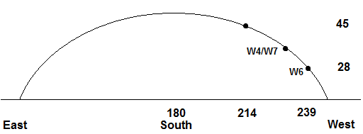
When you first found a satellite your elevation angle was very high, about 45 deg, so the satellite you found was approx 214 deg azimuth.
...
 You need to look about 25 deg further to the right to find the wanted lower elevation satellite. The line of satellites is sloping down towards the west.  Once you find a satellite peak up and note the position. Then try adjacent satellites either way: up to the left and down to the right.

Back to top
« Last Edit: Dec 26th, 2011 at 11:00am by Admin1 »  
WWW  
IP Logged
 
turana
Member
★★
Offline


Posts: 10
Reply #14 - Dec 26th, 2011 at 12:43pm  

...
in this picture is plastic holder in wrong side tied. the plastic holder must mounted to odu and feed suport between.

21°E — Eutelsat W6 (Eutelsat W3)
Ku-band Wide Beam
Distance to satellite:      39141km
Location:      34.6°N 69.06°E
Elevation angle:      25.5°
LNB Tilt (skew):      -47.2°
True azimuth:      243°

set your skew -47°

check your frequency , sembol rate ,22khz switch ,dvb mode parameter from the service provider.
Back to top
« Last Edit: Sep 13th, 2015 at 3:45pm by Admin1 »  
WWW  
IP Logged
 
Admin1
YaBB Admin
★★★★★
Offline


Posts: 1206
Reply #15 - Dec 26th, 2011 at 12:58pm  
Sorry I missed that
...
Get someone to hold the LNB/BUC/Feed assembly while you take out the plastic spacer and put it in its proper place between the tube and the baseplate.
This will affect the elevation angle.
Best regards, Eric.
Back to top
 
WWW  
IP Logged
 
afghan-gsm
Member
★★
Offline


Posts: 34
Reply #16 - Dec 26th, 2011 at 1:38pm  
thanx mr eric
it was my first mistak i did that if see the other picture it is there right place
Back to top
 
 
IP Logged
 
afghan-gsm
Member
★★
Offline


Posts: 34
Reply #17 - Dec 26th, 2011 at 2:01pm  
thank u all friends
one thing that now i notice that my Manual Commissioning page is difrent with the Manual Commissioning page wich i saw in this site
this is my Manual Commissioning page pic

and this is the picture i found from this froum
https://www.satsig.net/bentley-walker/hx/hx50-system-manual-commissioning.gif

some veules are not present in my commissioning page
Back to top
« Last Edit: Sep 13th, 2015 at 3:45pm by Admin1 »  
 
IP Logged
 
Admin1
YaBB Admin
★★★★★
Offline


Posts: 1206
Reply #18 - Dec 26th, 2011 at 2:22pm  
Your commissioning data should be exactly what you have been told for your site by your service provider.

Have they sent you a pdf page with all the information ?

You should have been told:

Your receive polarisation name.
Your receive frequency.
Your receive symbol rate.
22 kHz tone on/off.
plus much more such as IP addresses etc.

The information you use needs to be specific to your site now.  Data related to another site, some time ago, on a different satellite etc is of no use.

Best regards, Eric.
Back to top
 
WWW  
IP Logged
 
afghan-gsm
Member
★★
Offline


Posts: 34
Reply #19 - Dec 26th, 2011 at 3:25pm  
yes they send me all information
in one prp.rtf file
now the file incloud information that i dont know where to enter
for example
1.Frequency  Band /


now in my commessiton page this 1 point   there is not any place to enter this 1 point
Back to top
 
 
IP Logged
 
afghan-gsm
Member
★★
Offline


Posts: 34
Reply #20 - Dec 26th, 2011 at 4:14pm  
hello
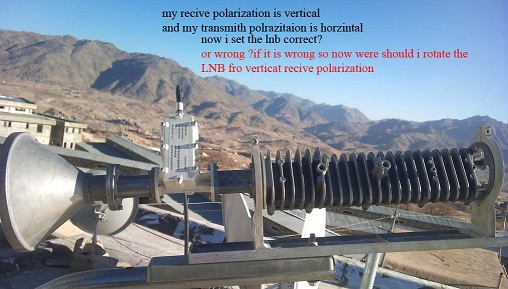
friends plz see this pic and tell me that  i selected correct vertical recive for my lnb or no
Back to top
« Last Edit: Sep 13th, 2015 at 3:46pm by Admin1 »  
 
IP Logged
 
Eric Johnston
Senior Member
★★★
Offline


Posts: 2109
Reply #21 - Dec 26th, 2011 at 4:35pm  
Put the modem receive tuning frequency in like this:
...
Please send me eric@satsig.net a copy of your prp.rtf file so I can see what you have been told. I can also talk to Bentley Walker (not far from here) and clarify any problems.

...
This shows the LNB BUC assembly turned in its yoke - which is not really a good idea as the 505 on the feed throat and single tick mark on the flange are no longer directly away from the feed support arm and the fat lump is no longer towards the feed support arm.

The polarisation orientation is completely wrong. You need Vertical polarisation name, adjusted by +47.7 deg clockwise, as viewed, looking forwards from behind the dish.

One option, which will get you working quickly but with poor cross-pol accuracy is as follow:
Turn the feed system in its yoke till the Universal LNB cable points straight up.  This is now Vertical polarisation starting position.  Now apply the adjustment amount.  Turn the feed system +47.5 deg clockwise, as viewed facing forwards towards the satellite in the sky. This is approx 90 deg clockwise from its present position in the picture above.

The correct option, which gives perfect cross-pol accuracy involves turning the LNB so that the cable points sideways.  The 505 on the feed throat and single tick mark on the flange are now directly away from the feed support arm and the fat lump is towards the feed support arm. Then turn the entire dish 90 deg anticlockwise, loosening slightly the 4 bolts at the rear and noting the 360 deg polarisation scale. The feed support arm is now on the right hand side, as viewed from behind the dish.  Then adjust the whole dish by an amount of 47.5 deg clockwise. The feed support arm will now be on the lower right as viewed from behind the dish.
Back to top
 
 
IP Logged
 
afghan-gsm
Member
★★
Offline


Posts: 34
Reply #22 - Dec 26th, 2011 at 6:03pm  
hello again
and so much sorry for my problem that i made problem for u friends

now in this picture https://www.satsig.net/bentley-walker/hx/hx-universal-lnb-buc-1.jpg the buc transmit polarization is vertical and recive polarization is horzintal in my case my buc trasmit polarization is horzintal and recive polarization is vertical now i can chang the velues from commissiong page i mean i shoul set the buc vertical and recive horzintal and setup my lnb like this picture
becuse i dont know to fix my lnb recive polarization to vertical


and in my PRP.rtf file there is Frequency  Band /      KU / QPSK
that in manoual commisson page there in no option for this
thanx
Back to top
 
 
IP Logged
 
Eric Johnston
Senior Member
★★★
Offline


Posts: 2109
Reply #23 - Dec 26th, 2011 at 7:07pm  
Your polarisation is set manually.  If you have been told correctly by the hub, then you need Vertical name receive, and Horizontal name transmit.

Entering of this information into the config screen sets the displayed information only. Your antenna equipment does not have a remote control polarisation change capability. You cannot change the polarisation using the screen.

The proper way to change polarisation is by manually turning the entire antenna 90 deg to change from Horizontal name start position (feed arm at bottom, LNB cable sideways) to Vertical name start position (feed support arm at the side and cable up/down).  You can then apply the adjustment : an amount of +47.5 deg clockwise rotation of the entire antenna, while behind the dish and facing forwards towards the satellite in the sky. Count the amount along the scale - ignore the numbers if they go backwards.

You can also change polarisation by rotating the LNB/BUC in its yokes but your antenna design (using asymmetric mode matched feed horn) is not designed for this to be done and it will cause bad cross-pol quality if the 505 and single tick mark are not directly away from the feed support arm.

Please send your PRP.rtf file to me at eric@satsig.net so I can see what you have been told and talk about your site with Bentley Walker, if necessary.

Best regards, Eric.
Back to top
 
 
IP Logged
 
afghan-gsm
Member
★★
Offline


Posts: 34
Reply #24 - Dec 27th, 2011 at 6:42am  
thanx mr eric
it is my to day work plz see this picturs
Back to top
« Last Edit: Sep 13th, 2015 at 3:46pm by Admin1 »  
 
IP Logged
 
Eric Johnston
Senior Member
★★★
Offline


Posts: 2109
Reply #25 - Dec 27th, 2011 at 10:11am  
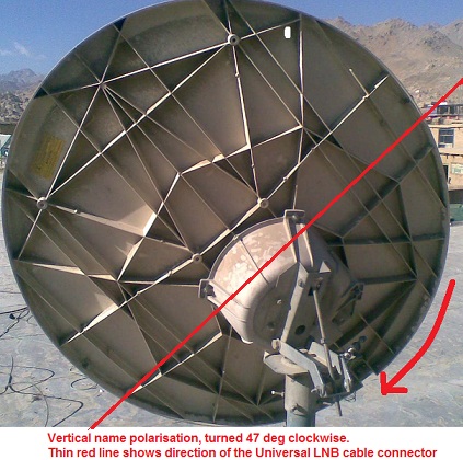
...
This looks perfect to me.
The thin red line show the direction of polarisation, the same as the direction of the Univeral LNB cable connector.

Now tighten the 4 polarisation plate bolts, check the elevation angle and swing to find a satellite.

Best regards, Eric.
Back to top
 
 
IP Logged
 
turana
Member
★★
Offline


Posts: 10
Reply #26 - Dec 27th, 2011 at 11:19am  
if you set skew from mount , then dont turn odu/lnb skew.
odu/lnb skew must set to 90 Vertical.
Back to top
« Last Edit: Sep 13th, 2015 at 3:46pm by Admin1 »  
WWW  
IP Logged
 
Eric Johnston
Senior Member
★★★
Offline


Posts: 2109
Reply #27 - Dec 27th, 2011 at 12:39pm  
I agree that the ODU should not be turned in its yokes.
The way he has the OMT joined to the adaptor tube puts the initial polarisation as horizontal when the feed arm is at the bottom.  To set to vertical start position he has turned the dish 90 deg anti-clockwise. Then applied the +47.7 clockwise adjustment - I hope. The picture abobe look promising to me.  I really hope it works after all this effort !

If he were to turn the OMT in its yokes till the LNB cable pointed upwards (with the feed arm at the central bottom position), he would get vertical polarisation start position but would have to undo the 12 hole flange and reattach the adaptor tube with the singe tick mark and 505 directly away from the feed support arm. He could then apply the 47.7 clockwise adjustment amount.

The critical thing with these asymmetric mode matched feeds is that the 505 must always be directly away from the feed support arm.  Behind the 12 hole flange you can in fact really do anything you want - any angle or even circular pol. Unfortunately it is not a free-rotation clamped joint and only allows 30 deg increments.

The use of the asymmetric mode matched feed gives better cross-pol perfomance than any other front fed offset antenna.

The LNB cable should be parallel to the red line.
The 505 and single tick mark should be directly away from the feed support tube.
The fat lump on the feed throat directly towards the feed support tube.

The purpose of the 505 to to indicate a +/- 5 deg range for allowable rotation of the ODU as a final tweeking adjustment, if necessary. In many cases an extra feed throat support is supplled and this limits the feed horn rotation by holding the fat lump centralised, with max 5 deg play either way.
...
See the feed throat support clamp in this picture which prevents the feed horn being rotated.

Best regards, Eric.
Back to top
 
 
IP Logged
 
afghan-gsm
Member
★★
Offline


Posts: 34
Reply #28 - Dec 27th, 2011 at 1:00pm  
so many thanx from all members and froum admin mr eric
i am disapred i think it is not possible to point with mapiex or singlal finder
and also becuse my english is not good i dont understand
it is my lnd picture after i made 47degree clackwies see it it is correct if it is not correct so plz describe i picture where should i fix the lnb cable
thanx

and also thanx mr eric for this picture can u tell me this dish is setup in wich stalaite in wich place and if possible other information
Back to top
« Last Edit: Sep 13th, 2015 at 3:47pm by Admin1 »  
 
IP Logged
 
turana
Member
★★
Offline


Posts: 10
Reply #29 - Dec 27th, 2011 at 1:57pm  
you have another choice ,for find this satellite ;
you need ;
tv and satelite recevier . connect recevier to lnb , set this parameter your recevier .
https://www.lyngsat.com/ew6.html

tv channel name :Baghdad TV Channel
frq:10972
pol:V
sembol rate:2170

search this tv channel in your satelite recevier. if find him then are you find right satelite.
Back to top
 
WWW  
IP Logged
 
Eric Johnston
Senior Member
★★★
Offline


Posts: 2109
Reply #30 - Dec 27th, 2011 at 2:51pm  
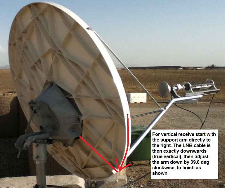
...
Wrong.
The LNB cable should be in the direction of the red line.

The 505 and single tick mark must be directly away from the feed support tube - ALWAYS.

The rotation of the entire dish is correct, as per the third figure below:
...

Tighten the 4 polarisation plate nuts at the rear, check the elevation and have a go at looking for some satellites. You will get reading with your simple meter on any satellite. You will get a reading up to 29 on your HX modem.  If the modem read out jumps up to approx 90 then you have the correct satellite and tuning etc.

I do hope they gave you correct information about you being to told to receive vertical name polarisation.

Best regards, Eric.
Back to top
 
 
IP Logged
 
afghan-gsm
Member
★★
Offline


Posts: 34
Reply #31 - Dec 28th, 2011 at 5:10am  
hello i have reciver supermax can i find this satalite via sample reciver if  yes i should chang the lnb or no if now i should select lnb universal?
And wich frequancy should i use to find the satalite thanx from all member and mr eric
Back to top
 
 
IP Logged
 
afghan-gsm
Member
★★
Offline


Posts: 34
Reply #32 - Dec 28th, 2011 at 9:37am  
hello to all
With sample reciver i can find hotbird 13degree and w7  just i cant find w6 21.5 it is realy strange i think the dish is small what u friends think
Back to top
 
 
IP Logged
 
Eric Johnston
Senior Member
★★★
Offline


Posts: 2109
Reply #33 - Dec 28th, 2011 at 9:40am  
If the wanted carrier is at 10972 MHz
You need to set the Universal LNB to low band.  I am niot sure if this is 22kHz tone on or off, so try both.
The local oscillator is 9750 MHz so you need to set your satellite receiver to 10972 - 9750 = 1222 MHz.

I don't really recommend looking for TV channel when you have a perfetly good HX modem already set up for your wanted HX internet service carrier.  The modem will indicate when the correct satellite and carrier are found (SQF approx 90), otherwise on any satellite it will give readings up to 29.  You have already successfully received a powerful satellite with a reading of 29, but this was much at a much higher elevation angle (45 deg) and 25 deg further round to the left from your wanted satellite.
...

Set the elevation accurately and then boldly swing the dish sideways. You will find a satellite on the first swing. Peak up, record the angles and check if it the satellite you want. While peaked up you can quickly try the alternative polarisation, tone on/off, frequency, symbol rate, etc.  If no success, try the next adjacent satellites either way along the orbit, slightly up left or slightly down right.

Best regards, Eric.

Back to top
 
 
IP Logged
 
afghan-gsm
Member
★★
Offline


Posts: 34
Reply #34 - Dec 28th, 2011 at 1:28pm  
hello to all friends to day i have tryed alot and no success with the hx medom finaly i serched satalite with super max reciver which is for tv with the hx lnb i found hotbird and w7 satelite and i contact with the support to change me on w7 they saied possible they send me new SBC. file and new frequncy and SPS 
i fixed the dish on w7 with simple setalite then i upload the sbc file and changed the frequncy and sps the high signall i got was 29 i think some think is wrong with my medom what u friends think
the dish was allready pointed on w7
Back to top
 
 
IP Logged
 
Eric Johnston
Senior Member
★★★
Offline


Posts: 2109
Reply #35 - Dec 28th, 2011 at 4:05pm  
Well done.

What TV program channel did you see on W7 ?

From that it should be possible to work out what polarisation you are receiving now.
...

Is the polarisation now the same as for the internet data service on W7 ?

For W7 you will need to set a new modem tuning frequency, symbol rate, 22 kHz tone etc.

The 29 shows that you have very strong signal power from a satellite.

The modem will not lock up on the wanted carrier, and the readout go up to SQF=90 approx, until:
  the modem receive frequency and symbol rate are correct
  the LNB 22 kHz tone is correct
  the sbc.cfg file is correct
  the polarisation is correct.

Best regards, Eric


Back to top
 
 
IP Logged
 
afghan-gsm
Member
★★
Offline


Posts: 34
Reply #36 - Dec 28th, 2011 at 4:17pm  
it is possible that my medom has problem becoz once i have mistacly upload the sbc file on the license place
and instad of mr eric question all info is ok sbc file is new frequncy is new just i dont know a bout this 22khz tone on of what is this for if can give me more information thanx
Back to top
 
 
IP Logged
 
Eric Johnston
Senior Member
★★★
Offline


Posts: 2109
Reply #37 - Dec 28th, 2011 at 6:20pm  
I assume you are pointed at W6 (at 21.5E) or W7 (at 36E) with max signal power of 29.

In case what you are told about 22 kHz tone is wrong, try with the 22kHz tone off and on.  This changes the LNB local oscillator frequency. One way should work. The other way will not work.

Polarisation: The adjustment angle for W7 (36E) is an amount of 38.6 deg clockwise. The adjustment angle for W6 (21.5E) is an amount of 47.7 clockwise.  These adjustments are applied after starting at either Vertical or Horizontal start positions, and viewed from behind the dish facing forwards towards the astellite in the sky.

In case the polarisation is wrong name, try altering the polarisation quickly.  Just turn the LNB/ORU in its yoke 90 deg or all the way round. There will be two good positions, opposite to each other. This only take a minute to complete the test.  The modem RX LED will light up whenever the polarisation is about right. Centre the range.

The tuning and symbol rate etc all should come from the rtf files you have been sent for each satellite.  After inputting the sbc.cfg file, does a "Universal" option appear in the LNB pull down menu ?    Power cycle your modem and look at the config screen.  The data displayed should still match what is on your sheet of paper (rtf printed out). If the "Save" function does not work and the old values are stuck, please say.  Is your modem an old one that has previously been used elsewhere ?

Best regard, Eric.
Back to top
« Last Edit: Dec 28th, 2011 at 9:04pm by Admin1 »  
 
IP Logged
 
afghan-gsm
Member
★★
Offline


Posts: 34
Reply #38 - Dec 29th, 2011 at 1:52am  
hello mr eric
yes this device is second hand and used in one cafe net and pointed on w6 in other place
and when i upload sbc file the lnb type automaticaly gos to universal
and one thing my support sayed u must do telnet first what is telnet and it is neccessery to eich time
and finall i think i fill the dish is and cant point to w6
mr eric i have sent u email see ur inbox my prp file see wich velue should use for 22khz on or off????? thanx you
Back to top
 
 
IP Logged
 
Eric Johnston
Senior Member
★★★
Offline


Posts: 2109
Reply #39 - Dec 29th, 2011 at 9:39am  
Please send me eric@satsig.net your rtf file for the W7 36E satellite.
You might also include both cfg files. Thanks.

Regarding you being told to use telnet.  I would rather not tell you how to do this without seeing your email (please forward).  If I tell you wrong it could stop your modem from working. You should only use telnet if told to do so by your service provider and then follow their instructions only.

The rtf file for W6 21.5E says 22 kHz tone should be ON.

Meanwhile make sure you can reliably find both the 21.5E and 36E satellites, noting for each the exact elevation and azimuth angles after peaking up (measure the lengths of the screws). I expect you will get a power reading of 29 on both satellites.

Best regards, Eric.
Back to top
 
 
IP Logged
 
afghan-gsm
Member
★★
Offline


Posts: 34
Reply #40 - Dec 29th, 2011 at 12:49pm  
hello mr eric now i have forward all needed content
and the new problem i face to day is when i am uploading SBC file then menul cammission and cliking on pointing the satelite  to see the signall strangh sudanly all  leds becom on for  1 second and after some second the system led become on and this massge came see the picture

now i cant point to satailte becoz this problem stoped my work i restar the hx medom and my lap top but the same what is wrong now?????
Back to top
« Last Edit: Sep 13th, 2015 at 3:47pm by Admin1 »  
 
IP Logged
 
Eric Johnston
Senior Member
★★★
Offline


Posts: 2109
Reply #41 - Dec 29th, 2011 at 1:47pm  
When you power the modem on, it does a self test sequence and all the LEDs probably light up for 1 second.

I can't see your image.

Back to top
 
 
IP Logged
 
afghan-gsm
Member
★★
Offline


Posts: 34
Reply #42 - Dec 29th, 2011 at 2:09pm  
hello
this is the picture link

when i power on the medom the only power is on when i connect the LAN cable the LAN led becom on and it is blinking when i enter https://192.168.0.1
 
Back to top
« Last Edit: Sep 13th, 2015 at 3:48pm by Admin1 »  
 
IP Logged
 
Eric Johnston
Senior Member
★★★
Offline


Posts: 2109
Reply #43 - Dec 29th, 2011 at 3:43pm  
If you are pointed at the wanted satellite, are receiving a good signal and have the transmit BUC connected, it is possible that the modem has been commissioned and it fully working OK.  If you have left it powered on for a long time with a good signal this may have happened.  If so, its IP address will have changed and you need to "repair" or "renew" your PC network adaptor so it uses the new IP address and subnet mask of your modem, as per the rtf file document.

I note that you were told by WAFA (in their email of 19th Dec) to reset your modem to factory settings using rf command.   You should only do this command if told to do so by your service provider and if your modem is not accepting (saving) new config data or not working properly.

Once you have done this you will need to re-enter all the parameters from your rtf page.

To do the rf command follow these PC instructions:

Start, All Programs, Accessories, Command Prompt.
You should see a black window.
Enter
telnet 192.168.0.1 1953
You should see a new line, then enter
rf

Best regards, Eric.
Back to top
« Last Edit: Dec 29th, 2011 at 6:42pm by Admin1 »  
 
IP Logged
 
afghan-gsm
Member
★★
Offline


Posts: 34
Reply #44 - Dec 29th, 2011 at 5:03pm  
hello
mr eric u r realy mastermind
i did the telnet wrongly
i did like this when open the CMD
i wrote this
telnet 192.168.0.1 1953rf    this  was my fault
if it can makes this problem that i cant recive the signal i am sure this was my problem
but the other i dont know why in my manual commission page this value dont exist or it is not important
Frequency  Band /       KU / QPSK
Back to top
« Last Edit: Dec 29th, 2011 at 6:43pm by Admin1 »  
 
IP Logged
 
Admin1
YaBB Admin
★★★★★
Offline


Posts: 1206
Reply #45 - Dec 29th, 2011 at 6:41pm  
telnet 192.168.0.1 1953rf
If you did that mistake  there was probably an error and there was no effect.   The modem was not reset.

Frequency  Band /       KU / QPSK
Don't worry if there is no place to input this data.

Best regards, Eric.
Back to top
 
WWW  
IP Logged
 
turana
Member
★★
Offline


Posts: 10
Reply #46 - Dec 29th, 2011 at 8:37pm  
i think he use windows7 , telnet service is not installed as defautlt setting.
if u have windows xp
click-star
click-run
scribe - cmd and press enter
if is opened dark window , use this command "telnet 192.168.0.1 1953"
press 3 time enter ,
scribe "cim" or "dim" i dont remeber try it , press enter
and see menu.
use "rf" command
modem will reeboot. and modem turn back to factory seting.
Back to top
 
WWW  
IP Logged
 
afghan-gsm
Member
★★
Offline


Posts: 34
Reply #47 - Dec 30th, 2011 at 2:21am  
Quote:
i think he use windows7 , telnet service is not installed as defautlt setting.
if u have windows xp
click-star
click-run
scribe - cmd and press enter
if is opened dark window , use this command "telnet 192.168.0.1 1953"
press 3 time enter ,
scribe "cim" or "dim" i dont remeber try it , press enter
and see menu.
use "rf" command
modem will reeboot. and modem turn back to factory seting.


hello thanx from ur help can u tell me can i use hx50 frquncy ans sps in sample dish to find satelite or i should find frequncy of tv
Back to top
 
 
IP Logged
 
afghan-gsm
Member
★★
Offline


Posts: 34
Reply #48 - Dec 30th, 2011 at 2:36am  
Quote:
telnet 192.168.0.1 1953rf
If you did that mistake  there was probably an error and there was no effect.   The modem was not reset.

Frequency  Band /       KU / QPSK
Don't worry if there is no place to input this data.

Best regards, Eric.

thank you mr eric
a new qusetion wich one of this setalite is power full w6 or w7 to point toward
Back to top
 
 
IP Logged
 
Eric Johnston
Senior Member
★★★
Offline


Posts: 2109
Reply #49 - Dec 30th, 2011 at 1:16pm  
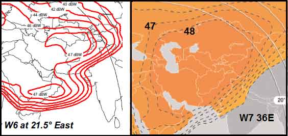
...

W7 transponders have 1 dB higher downlink eirp power towards Afghanistan.  Your elevation angle to W7 will be higher.

Note that the power of your carrier is set by the transmit hub site.  The power may not be in proportion to the transponder saturated output power. Downlink power is adjusted to suit the smallest receive earth station in the network.

If you measure the HX downlink carrier on both satellites please say what SQF you measure on each when peaked up.

Best regards, Eric.  
Back to top
 
 
IP Logged
 
afghan-gsm
Member
★★
Offline


Posts: 34
Reply #50 - Jan 2nd, 2012 at 11:11am  
thanx from all friends finally I pointed the dish with 94 signal and now I have internet just I want to know I took soho512 pakage can any one tell how much will the download per sec in KB no kb thanx
from mr eric that helped me a lot thanx
Back to top
« Last Edit: Jan 2nd, 2012 at 12:50pm by Admin1 »  
 
IP Logged
 
Pages: 1