Advertisment: Broadband via satellite
Advertisment: Worldwide satellite services from Ground Control Company

www.satsig.net

Satellite Internet Forum.

Welcome, Guest.        Forum rules.
      Home            Login            Register          
Pages: 1

Using a datastorm dish with tooway

(Read 10416 times)
grahamess
Member
★★
Offline


Posts: 4
UK
Mar 23rd, 2013 at 8:07pm  
Has anyone got experience of putting a tooway KA tria onto a data storm dish. Appreciate it may not auto deploy but can it be used to manually use the motorised dish to align to the satellite
Back to top
 
WWW  
IP Logged
 
Eric Johnston
YaBB Moderator
★★★★★
Offline


Posts: 2109
Reply #1 - Mar 27th, 2013 at 10:08am  
All earth stations in the Tooway system must comply with the KA-SAT Tooway inter-system coordination agreements with regards to off-axis sidelobes and cross-pol isolation. In addition, Tooway impose their own rules on transmit gain and receive G/T. The objective is to avoid unacceptable interference to or from other satellite users, at the same frequencies.

The only realistic and legal way you can meet the requirements is to use the standard Tooway reflector, feed support arm and feed/RF module.

I doubt there would be any objection to using a steerable mount, with an attached complete Tooway antenna and RF module. Just make sure it is stable and does not wave about in the wind !

Note the following:

Antenna surface accuracy needs to be better than 1/10th wavelength.  At 30 GHz the wavelength is 10mm, so surface accuracy must be 1mm or better. This is very difficult to achieve and dishes must be transported and handled very gently indeed. Wire mesh dishes are fine for low frequencies like L band.  For C band and Ku band, a fine wire mesh can be acceptable.  At Ku band perforated metal sheet is OK.  For Ka band, a solid continuous metallic surface layer is needed.

Feed horns distribute their power across the dish surface, with power density being higher in the middle and lower at the dish edge.  Typically the edge taper will be around -16 dB relative to the dish centre.  This is key to low off-axis sidelobes and pick up of minimal thermal noise from the ground. If the F/D ratio of the dish is small the feed horn is close to the dish and must spread its energy wide. Such feeds typically comprise an open circular waveguide with, possibly adjustable, scalar rings.
If the F/D is higher the feed is further away from the dish and the feed must project its power into a smaler angle.  Such feeds are normally conical horns and have a larger aperture diameter.
For VSAT use, the feed horn and the reflector dish are highly interrelated and should not be swapped about.


Best regards, Eric
Back to top
 
 
IP Logged
 
grahamess
Member
★★
Offline


Posts: 4
UK
Reply #2 - Mar 27th, 2013 at 10:31am  
Thanks Eric,
That is kind of where we were thinking. Just using the motosat/datastorm motor/mechanism as a steerable mount. The intention was to then mount our regular dish and tria onto this, having made a folding feed arm for the tria. May be more hassle than its worth, we just have access to an old Datastorm mount.
bests, Gra
Back to top
 
WWW  
IP Logged
 
Eric Johnston
YaBB Moderator
★★★★★
Offline


Posts: 2109
Reply #3 - Mar 27th, 2013 at 11:23am  
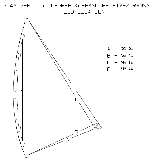
If you devise your own feed support arm be aware of the need for very high accuracy of the distances from the lower and upper rims of the feed horn aperture to the lower and upper central edges of the dish. These four measurements are known as A, B, C and D.  See example details below for a larger dish
...

The feed obviously needs to be in the middle, sideways !

If it were possible to point the feed towards the dish it would be aimed at, or just a fraction above, the physical centre.

Best regards, Eric.
Back to top
 
 
IP Logged
 
grahamess
Member
★★
Offline


Posts: 4
UK
Reply #4 - Apr 15th, 2013 at 9:37pm  
Thanks for those figures Eric. It may be more hassle than its worth. Just a play project in spare time though.
Gra
Back to top
 
WWW  
IP Logged
 
Eric Johnston
YaBB Moderator
★★★★★
Offline


Posts: 2109
Reply #5 - Apr 15th, 2013 at 10:33pm  
Using the original feed support arm measure and make a record of the exact ABCD measurements for the Tooway dish and supplied feed/feed support arm.

Keep to those measurements on any self-made support arm.

Preferably keep on using the standard support arm and use your own postioner to point the entire dish and feed support arm.

Best regards, Eric.
Back to top
 
 
IP Logged
 
Admin1
YaBB Admin
★★★★★
Offline


Posts: 1203
Reply #6 - May 7th, 2016 at 1:41pm  
Posted here by forum admin, from an email...

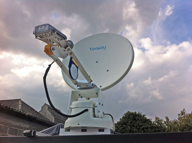
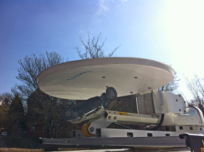
"Two years ago I came across the above discussion in this forum. It encouraged me to seek out a Motosat pan and tilt mechanism and adapt it for use on KA sat. Paying close attention to Eric's advice  I used the original arms cutting them carefully to length so I maintained the dish to LNB relationship shown in Eric's drawing.

...

The hinge is made from aluminium milled from a solid block. This has to be very accurately made to maintain the angle to the dish when elevated.

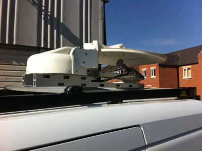
I added a roller which I sourced from Ebay. To enable the dish to fold fully horizontally the motor has to be raised at least 82 mm above the roof of the vehicle. The machine shop produced a aluminium frame for this purpose which the motor bolts onto.

It took two years to source a motor, find a CAD designer and a metal work shop willing to work on a project that was a little off the wall.

... ...

The dish is not self-seeking but once you have set the elevation of the bird it takes just over 5 mins to get online.

It is thanks to Eric and the other contributors to this article that made this possible."

Note by forum admin: If you want to contact the originator, please email me eric@satsig.net and I will pass the message on.
Back to top
« Last Edit: May 8th, 2016 at 8:55pm by Admin1 »  
WWW  
IP Logged
 
Pages: 1