Advertisment: Broadband via satellite
Advertisment: Worldwide satellite services from Ground Control Company

www.satsig.net

Satellite Internet Forum.

Welcome, Guest.        Forum rules.
      Home            Login            Register          
Pages: 1

AUPC Miteq Uplink Power Control Alarm

(Read 5491 times)
Zakki
Member
★★
Offline


Posts: 5
Dec 14th, 2015 at 10:39am  
Gents,

Have any one faced the alarm Miteq UPC Receiver input A Alarm on STEE dashboard & how to clear it?

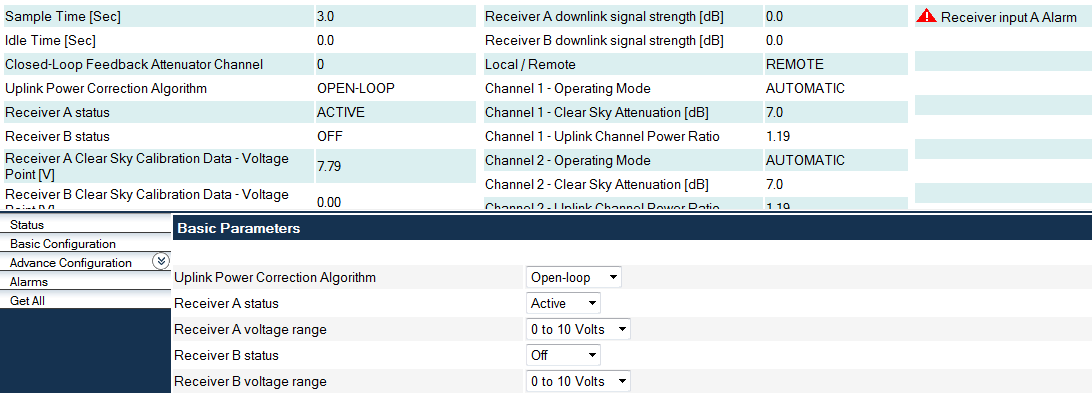
In dashboard monitoring, it's giving me major alarm on the AUPC equipment & in NGC IDU, it's giving faulty of receiving UPC inputs (SS attached).

The actions that have been taken:

Checking all AUPC connections & it’s connecting properly.

Thanks in advance.
Back to top
« Last Edit: Dec 15th, 2015 at 10:40am by Admin1 »  

NGC_SS.png (158 KB | 275 )
NGC_SS.png
 
IP Logged
 
Admin1
YaBB Admin
★★★★★
Offline


Posts: 1203
Reply #1 - Dec 14th, 2015 at 10:54am  
What is the normal, clear sky, input voltage level to the UPLINK POWER CONTROL SYSTEM ?

The UPC needs to be set to accept either 0 to +10 volts input or 0 to -10 volts input. Beacon voltage level goes in on J1.

There is a receiver status input also, such that if your beacon receiver becomes faulty it can tell the UPC that any signal voltage provided is invalid. This fault signal is on J9 connector. For the Receiver A status input, pins 1 and 3 refer. The input fault indication is user-configurable as either a contact closure or a contact open.

Read more: https://miteq.com/docs/29TEC.PDF
Back to top
 
WWW  
IP Logged
 
Zakki
Member
★★
Offline


Posts: 5
Reply #2 - Dec 15th, 2015 at 7:48am  
Thanks Yabb for your feedback.

All setting are configured as the default values: clear sky 7 dB, voltage range: 0 to 10 V, as per the attached SS.

Receiver A Clear Sky Calibration Data is 7.79 dB.
Back to top
 

2015-12-15_104633.png (21 KB | 301 )
2015-12-15_104633.png
 
IP Logged
 
Admin1
YaBB Admin
★★★★★
Offline


Posts: 1203
Reply #3 - Dec 15th, 2015 at 10:16am  
It looks like you have a good clear sky signal voltage (about 8 volts) and that the UPC input range 0 to +10 volts is set correctly.

You have got Receiver Status A set to active.

This means it will give a display (i.e. FAIL or OK) depending on the connections to pins 1,3 on connector J9. It is expecting a pair of relay contacts, either closed or open under FAIL conditions.

What do you have connected to J9 ?

If your receiver has a fault alarm on it, with relay contact closure or open, then these two wires need to go from the receiver to the Uplink Power Control connector J9.  The beacon receiver might have a power fault (e.g. be switched off) or have lost lock on the beacon signal, in which case the output voltage (0 - 10 volts) would go to zero, but this would be an INVALID dB level and MUST NOT cause the UPC to massively increase your uplink transmit power to the satellite. The receiver FAIL status tells the UPC to continue with nominal transmit level when the beacon receiver becomes faulty.

On the UPC, the options for Receiver A status are probably:
Active
Inactive

If you switch this to Inactive and the alarm goes away you have at least isolated the cause. But don't just leave it like that. You would be hiding a serious hazard!

Under advanced configuration there may be:
Receiver A Status open circuit = FAIL
Receiver A Status closed circuit = FAIL

It is important that the UPC should not spuriously increase your transmit power to the satellite when your beacon receiver is powered off, beacon receiver has failed or complete loss of beacon signal, so try and get the two wires connected up and the open/closed circuit options set right.
Back to top
 
WWW  
IP Logged
 
Zakki
Member
★★
Offline


Posts: 5
Reply #4 - Dec 16th, 2015 at 12:49pm  
Hi & appreciate your investigation.

Tracing receiver is working properly [No fault alarm on it].
What about loosing of beacon signal, how to re-tracking the normal value?

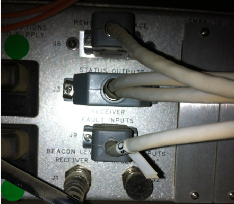
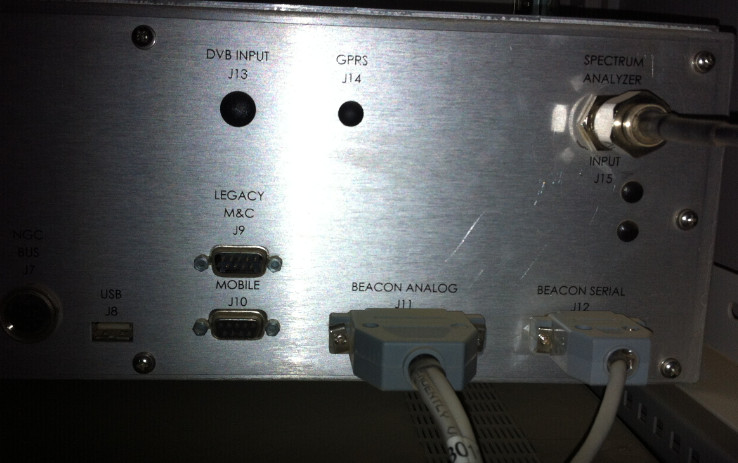
Connector J9 is connected to beacon analog as per labeling.
Back to top
 

2015-12-16_154502.jpg (51 KB | 291 )
2015-12-16_154502.jpg
2015-12-16_154430.jpg (109 KB | 291 )
2015-12-16_154430.jpg
2015-12-16_154528.jpg (51 KB | 287 )
2015-12-16_154528.jpg
2015-12-16_154629.jpg (81 KB | 276 )
2015-12-16_154629.jpg
 
IP Logged
 
Admin1
YaBB Admin
★★★★★
Offline


Posts: 1203
Reply #5 - Dec 16th, 2015 at 6:51pm  
I can see the plug going into J9 on the AUPC.

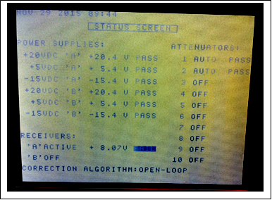
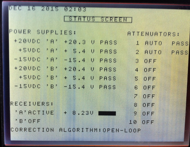
I note the receiver is working well. Power is good. Signal is locked.  Signal level as shown on the AUPC 8.23 volts looks good. It would give you confidence if moving the antenna causes this voltage to change exactly as you expect.  Is there a calibration scale like 1 volt = 2 dB or 1 volt=3dB .. ?

You could test, using a calibrated switchable attenuator, 1, 2, 3, 5, 10, 20 dB on the beacon receiver input. The output voltage should go down by the equivalent amounts. Turn off the UPC effect while you do such a test.

Read the receiver manual to check that -61.6 dBm is a reasonable input level. You need about 20 dB linear dynamic range down from this. The input level to the beacon receiver depends on where it is connected in the L band splitter distribution system.

If any receiver fault (loss of power, loss of signal lock) occurs there should be a contact open or contact closure on a pair of wires which should come from the receiver (possibly J11?) to the AUPC (J9).


The other end of the cable to input J9 appears to be connected from Beacon Analogue output plug J11 on the receiver. Cable #30. There are two cables, the other cable is presumably the coax, carrying the analogue 0 to +10 volts.

Read the receiver manual to find out what its alarm output contacts do. The receiver contacts outputs may be connected to pins 1,2 or 4,5 or the alarm may be opposite sense, e.g. open circuit instead of closed circuit or vice versa. There may even be a configuration in the receiver so that a fault condition causes open or closed circuit on the alarm output.
Back to top
« Last Edit: Dec 17th, 2015 at 10:02am by Admin1 »  
WWW  
IP Logged
 
Zakki
Member
★★
Offline


Posts: 5
Reply #6 - Dec 28th, 2015 at 8:20am  
Thanks a lot Admin1 for your replay & investigation.

We have arranged for MDT to check all the connectivity, voltage & HW for the sys.

I'll keep you updated.

Regards.
Back to top
 
 
IP Logged
 
Pages: 1