How to do it:If you have three modulators you may combine the outputs into one cable using a passive splitter/combiner device. If you get a 4 input port version, put a dummy load on the spare input.
Splitter/combiners are available for 70MHz IF, 140MHz IF and L band IF.
Upconverters may be 70 MHz, 140 MHz or L band IN and C, Ku or Ka band OUT. Note that 70 or 140 MHz input upconverters are narrow bandwidth and you will need multiple upconverters if you want to transmit into several transponders, plus a C, Ku or Ka band combiner just before the HPA.
Why 3 carriers ?It is far better to transmit one big carrier. Put all the traffic on one carrier if possible.
You may need to transmit multiple carriers if you are operating into several cross-strapped transponders. For example if you are in a Europe uplink beam and want to send signals to a Europe downlink beam, a S. Africa downlink beam and a S. America downlink beam. In this case you need to transmit three carriers.
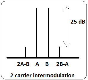
The big problem: Intermodulation interference.If you put more than one carrier through an HPA it causes intermodulation interference on nearby frequencies. To keep this interference to an acceptable low level you need to operate your HPA in its linear region, which means its output backed off from its single carrier maximum operating point.

A nominal 400W HPA may be good for 1 carrier at 400W but in multi-carrier operation it needs to be backed off sufficiently. 3 dB output back off (OBO) would make it good for two 100W carriers or three 67W carriers or four 50W carriers. This is clearly not good in terms of HPA cost, power cost and cooling. Talk to HPA manufacturers about advanced linearised HPAs which may be operated nearer saturation. It is mandatory that you have means of monitoring your HPA output spectrum so as to send spectrum plots to the satellite operator. You need a high loss cross waveguide coupler, SHF spectrum analyser and plotter.


