An LNB with a circular or square waveguide input will normally be able to receive two linear polarisations, at right angles to each other, using a power supply selection voltage 13v or 19v. This is normal for satellite TV reception.
An LNB with a rectangular waveguide input (as used for Ku band VSATs) will be able to receive one linear polarisation only. The plane of polaristaion is at right angles to the wider dimension.
So this is set for vertical polarisation. The polarisation is the same as the half dipole pin inside.
An LNB with a coax SMA input has no polarisation. It is simply a low noise amplifier, mixer and IF amplifier.
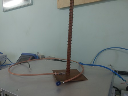
If such an LNB, with a coax SMA input, is connected to an antenna it is the antenna that defines the polarisation. If the coax connector is connected to the middle joint of a vertical dipole antenna then the polarisation being received is vertical. If the coax connector is connected to the end of an axial-mode helix antenna then the polarisation being received is circular and the choice of polarisation (clockwise or anticlockwise) is fixed permanently by the physical construction of the helix. This might apply to the reception of maritime satellite L band signals.
UHF and L band satellites normally use circular polarisation as the signal polarisation is dynamically rotated in the ionosphere (called Faraday rotation). If linear was used the signal levels would be varying dramatically.
Most Ku band satellite TV signals are linear polarisation, but there are a few popular systems in the USA that use circular.
Most 20/30 GHz Ka band satellites use circular polarisation, to make life easy for the installers. Having a polariser costs a bit more but eliminates a skill requirement for installers, as adjusting linear polarisation angle accurately is difficult and extremely important in transmit/receive VSAT systems.
In both Ku (10-14 GHz) and Ka (20-30 GHz) band the use of a helix feed would be unusual. Normally such reception is done using a circular or square waveguide between the feed horn and the LNB, with the waveguide section containing a polariser which is either a dielectric plate at 45 deg or sets of castellations and slots on opposite sides inside the guide, also at 45 deg. In such cases what receive signals that appears after the polariser and going into the LNB are two linear polarisations, which may be selected using a normal dual-polarisation LNB using 13v or 19v.
If you have a low noise amplifier (LNA) or LNB, with a coax SMA input, and want choice of two circular polarisations you might have two helix antennas (wound with opposite senses) which you manually dis-connect and swap over.
I hope that helps. Does anyone have any pictures to contribute, for example: Amateur radio?.
Best regards and Happy Christmas, Eric.