Advertisment: Broadband via satellite
Advertisment: Worldwide satellite services from Ground Control Company

www.satsig.net

Satellite Internet Forum.

Welcome, Guest.        Forum rules.
      Home            Login            Register          
Pages: 1

Prodelin 1383 conversion possibility to DTH LNB mount

(Read 3564 times)
PETER
Member
★★
Offline


Posts: 2
Kerala, India
May 9th, 2020 at 6:34pm  
I am in India got two Prodelin 1383 3.8M VSAT dish units, got from a Government auction. As an Amateuer Radio operator I am trying to fix these satdishes for accessing QO100 Eshailsat at 26 degree E. I reassembled the dish units as per the OEM manuals with 23 degree shift etc. We have to remove the whole electronics including the C /Ku LNB assys and mount a normal small Ku band DTH LNB for the reception of Beacon and hence the alignments.

All our efforts to bring the focus to the point  on the LNB stand fails. We could receive the signal at 12-16inches right to the LNB stand, with a less quality. 1.3M standard Prime focus DTH metalic dish give better reception reading.

In normal mount the dish is almost vertical to track the 26E.
So we tried to Invert. Now the LNB is above and still no luck.

Request support. Does anyone tried these dish units for DTH LNB mount?
When we use a different LNB, will the focus point / gain shift?
The Prodelin Brochure say Prime focus, offset feed
can I convert this to a Prime focus, with a new LNB tripod?

Guide me a way where I can tap the max gain for my project, out of such a great sat dish.

Tnx in advance, to all comments and opinions...
Back to top
 
 
IP Logged
 
Admin1
YaBB Admin
★★★★★
Offline


Posts: 1203
Reply #1 - May 9th, 2020 at 10:15pm  
Two things to check.

1. Is the dish intended for Ku band operation?.  Some old dishes are for C band and have coarse wire mesh embeded in plastic.  The mesh size may not be good for Ku band. I have not yet had time to find the spec for Prodelin 1383.

2. The next thing to check is dish reflector assembly.  The rim must be flat to 1/10 wavelength.

Do the crossed strings test. Put one tight fishing line or thin strong string up and down the middle. Put a second line tight sideways and see how they cross. They should just touch and there should be no gap. If it is a 4 panel dish, repeat the test with the strings offset 45 deg.

I am not sure quite how the Prodelin 1383 3.8m dish is made, but I have come across a similar dish with 4 segments and it was completely useless due to incorrect assembly, even though at a distance it looked quite normal. It was due to using wrong bolt lengths and then forcing the panels together. There were 1mm gaps in the panel joints, which they had obscured with mastic.  It cost a fortune to send someone half way round the world to fix it.  Put right it worked perfectly.  Assembling such large dishes is highly skilled as it requires both great precision delicacy and at the same time involves quite heavy parts. Precision in rim flatness is critical.

If you fail the result is possibly 5dB to 10 dB low gain and hopeless beam pattern with more than one 'main beam' and apalling sidelobes which collect noise and interference and make trasmission illegal.

Regarding the focal point and how to position a Ku band LNB feed horn, I will help on this tomorrow.

Eric
Back to top
 
WWW  
IP Logged
 
PETER
Member
★★
Offline


Posts: 2
Kerala, India
Reply #2 - May 10th, 2020 at 6:45am  
Thank you for the response.


Two things to check.

[i]1. Is the dish intended for Ku band operation?.  Some old dishes are for C band and have coarse wire mesh embeded in plastic.  The mesh size may not be good for Ku band. I have not yet had time to find the spec for Prodelin 1383.

[/i]


I have two, one was with C band and one was with KU band hardware. I will try to share the available photos. You have given me a new light....I will change the reflectors and see the result in couple of days time.

2. The next thing to check is dish reflector assembly.  The rim must be flat to 1/10 wavelength.


I done this for the major and minor axis....offset 45 degree I will try


I am not sure quite how the Prodelin 1383 3.8m dish is made, but I have come across a similar dish with 4 segments and it was completely useless due to incorrect assembly, even though at a distance it looked quite normal. It was due to using wrong bolt lengths and then forcing the panels together. There were 1mm gaps in the panel joints, which they had obscured with mastic.  It cost a fortune to send someone half way round the world to fix it.  Put right it worked perfectly.  Assembling such large dishes is highly skilled as it requires both great precision delicacy and at the same time involves quite heavy parts. Precision in rim flatness is critical.


Yes! It is very tricky. We assembled the 4 sections, over the mounting pedestal. There is 12  sleeves mounted on the sections, 3 each in one section. All these are with different lengths. We checked the numbering as per the OEM manual all OK. we mounted the dish to the pedestal and missed to place a spacer. On later inspection we realised that the spacer play a major role in keeping the reflecting surface accuracy. We done it correctly afterwards. If the spacer is missing then the gap between the sections appear slowly.

I will check the rim flatness.


Regarding the focal point and how to position a Ku band LNB feed horn, I will help on this tomorrow.

keenly waiting for more from you, Prodelin 1383 manual is freely downloadable, please find little time for me.  Regards

Peter
Back to top
 
 
IP Logged
 
Admin1
YaBB Admin
★★★★★
Offline


Posts: 1203
Reply #3 - May 10th, 2020 at 9:00am  
You are right about the bolts and spacers.  That was the problem on the dish I referred to above. It was not the length of the bolts but the length of the spacers.

More thoughts about crossed strings tests.  With a 4 panel reflector you need an additional test with an extra pair of strings:  pair up/down/across plus a pair at 45 deg. All four strings should touch.

There are several possible types of distortion.

The sides can be pulled forwards or pushed back due to the weight of a heavy feed assembly pulling on the side struts.  It depends on the elevation angle. Worse after long time in hot locations. Common problem for plastic dishes. 

If the main feed support strut (at the bottom) is attached to a metal spine up the back then there is the possibility of the lower edge of the dish being attched to the feed support strut.  If this is the case, the bolt should simply drop in and not force the lower edge of the dish forwards or backwards.

With 4 panels it is possible for each panel to be mispointed inwards or outwards from the intended main beam direction.  Thus the need for extra tests so that the up/down/across and 45 deg strings ALL touch.

Rim flatness is the key to obtaining the intended performance.

Eric.
Back to top
 
WWW  
IP Logged
 
Admin1
YaBB Admin
★★★★★
Offline


Posts: 1203
Reply #4 - May 10th, 2020 at 9:26am  
About the focal length and positioning the feed horn.

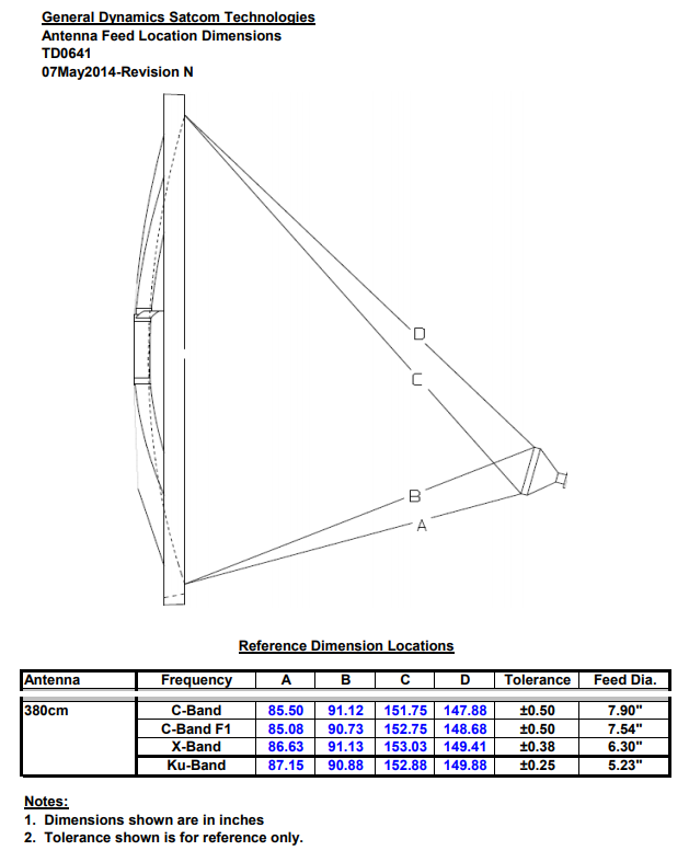
There are 4 distances: ABCD.

A   From the bottom of dish to bottom of feed horn aperture.
B   From the bottom of dish to top of feed horn aperture.
C   From the top of dish to bottom of feed horn aperture.
D   From the top of dish to topof feed horn aperture.

Example for 380cm dish with Ku band horn 5.23 inches diameter.
A  87.15 inches
B  90.88  inches
C 152.88 inches
D 149.88 inches

...
There have been revisions of such ABCD figures and I have uncertainty about exactly what figures refer to older models of antenna and feed horn type. 

...

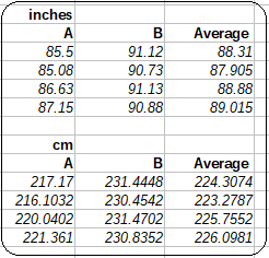
If you average A and B you get the distance from the lower curved edge of the dish to the centre of the feed window.  The shortest distance presumably refers to a feed with a phase centre down inside the feed horn.  The longest distance presumably refers to a feed with the phase centre very close to or at the aperture.

Feed horns don't have clearly marked phase centres.  The phase center can be in the middle of the aperture or down inside the horn somehere. It can move in and out with frequency.  A very long slowly tapered horn or open ended waveguide has the phase centre at the aperture. A medium wide angle flare horn can have its phase centre inside.

The diameter of the feed horn affects its beamwidth. The beamwidth should be -10 dB down at the dish edge for receive only system with no interference from nearby satellites. e.g. moonbounce at high elevation angle.   The beamwidth should be about -16 dB down at dish edge for best compromise of gain and low sidelobes, so minimal interference from other satlliote and ground pick up noise at low elevation angles.

For an offset dish, aim the feed just above the dish centre.

I have no idea where is the phase centre is of a typical Ku band LNBF with a short horn.

If you get it working very well I would not worry too much about perfection in focus. To try and perfect the focal length you need to plot the main beam pattern and first sidelobes at least 4 times at different distances in both azimuth and elevation and then interpolate for the most deep nulls.

Eric
Back to top
« Last Edit: May 10th, 2020 at 2:39pm by Admin1 »  
WWW  
IP Logged
 
Admin1
YaBB Admin
★★★★★
Offline


Posts: 1203
Reply #5 - May 10th, 2020 at 2:42pm  
There is more here https://www.satsig.net/axiflat.htm relevent to alignment of 12 panel dishes.
Back to top
 
WWW  
IP Logged
 
Pages: 1