|
|
Focal length of parabolic dish. How to find offset angle of dish Picture of a feed assembly with transmit and receive connections |
Explanation of Polarisation Angle.
Definition of Polarisation ( also known as skew or polarization )
Vertical polarisation is when the electric field is vertical. When people talk about polarisation they are referring to the electric field vector. References to 'vertical' and 'horizontal' are frequent since terrestrial antennas are normally vertical or horizontal relative to the ground.
Example 1: Vertical polarisation is produced by a vertical dipole antenna. At an instant, the top is positive voltage and the bottom is negative voltage - so the electric field produced is vertical.
![]()
Vertical polarisation from a quarter wave dipole in a rectangular waveguide.
Example 2. Vertical polarisation is produced by the open end of a rectangular waveguide whose narrow dimension is vertical and whose broad face is horizontal. The waveguide is typically energised by a vertical probe (like a single ended quarter-wave half of a half-wavelength dipole antenna) sticking through the broad face of the waveguide. Inside the waveguide think in terms of voltage between the centre lines of the two broad faces. This is the vertical electric field. Around the two narrow sides, current flows. It does not matter if the pin is at the top, pointing downwards, or at the bottom pointing upwards, in either case it is still vertical polarisation.
To set nominal Vertical receive polarisation the broad faces of the LNB waveguide must be on top and underneath.
These diagrams above show your view facing towards the satellite. Your viewpoint is from behind the dish looking forwards towards the satellite. You can see the feed horn window. The rectangular LNB receive waveguide is shown. Note the four possible starting positions in the top row. You then apply an adjustment, between -90, 0 and +90 deg, anticlockwise or clockwise. A -45 deg adjustment is shown as an example. Sometimes the LNB will hit the metal feed support arm when you apply the adjustment; in this case start again with the alternative starting position, on the other side.
A few satellites (notably Astra and Eutelsat) were not constructed with their polarisation angles aligned accurately north-south. In the case of Eutelsat II Ku band and W Ku band you need to add +3.5 degrees to the calculated results, i.e. turn it a bit more clockwise to the right. In the case of Astra satellites add + 7 degrees clockwise rotation, while facing the satellite. The reason for this was to make the polarisation adjustment amount, as received on the ground, nearer to zero in the central region of the coverage beam. This reduces cross-polar interference in rain.
Two polarisations (at right angles to one another) are often used simultaneously to provide two fold frequency reuse and this applies in both the uplink and down link frequency bands.
VSATs normally transmit on one polarisation and receive on the other.
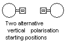
Two alternative vertical polarisation starting positions.
If you rotate the feed by 180 degrees you are back to the same polarisation as when you started. This is useful to know as rotation of the feed may cause metal parts to knock into each other. In these circumstances start your adjustments from the opposite 180 degree position.
Vertical polarisation starting position with +6 deg adjustment applied.
Polarisation angle should be optimised to an accuracy of +/- 1 deg to reduce interference on the opposite polarisation to an acceptable level. This is particularly important for transmitting antennas and for receive-only antennas trying to receive digital carriers.
For transmit antennas, the hub will normally request the transmission of a low power un-modulated carrier on a carefully selected frequency. They will ask you to rotate the feed around the optimum angle while they observe for the very sharp null in the cross polar signal, using a spectrum analyser with a narrow resolution bandwidth (say 30 Hz). You may well need to turn the feed slowly in steps of 0.5 deg to find the best position.
To optimise polarization angle by practical measurement on receive-only is more difficult since the co-polar wanted signal has a very broad maximum. If you can measure receive quality such as Eb/No, C/N or BER with a fine degree of resolution (e.g. Eb/No in 0.1 dB steps) and can accurately measure the angle of the feed a good method is to degrade the receive quality by a substantial amount, say about 4 dB down. Record the degraded quality accurately and the angle of the feed accurately. Then turn the feed a similar amount on the other side and adjust for exactly the same degraded quality. Record the second angle and set the feed to the calculated mid point. This will normally give an accuracy of +/-1 deg, particularly if you repeat the process several times and average the results from several pairs of angle/quality measurements. This method does not work if there are interfering cross polar signals that are varying in level all the time. Feed rotation angles may be recorded using a strip of paper wrapped around, with the half way point being marked up while it is temporarily removed.
![]()
LNB rectangular waveguide input.
Oriented for horizontal polarisation starting position.
|
Page started 1998, last amended 15 April 2018 This page is copyright 1998 Satellite Signals Ltd All rights reserved. |