Advertisment: Broadband via satellite
Advertisment: Worldwide satellite services from Ground Control Company

www.satsig.net

Satellite Internet Forum.

Welcome, Guest.        Forum rules.
      Home            Login            Register          
Pages: 1

-7 tx power. sorta scary!

(Read 8290 times)
Ex Member
Ex Member


Feb 26th, 2008 at 8:04pm  
I am very annoyed by the fact that my TX power is at -7.
I've always heard that higher than -8 ( so -7 is higher than -8 ) is bad for the BUC.

Is there a need to worry now or how do i diagnose this issue?

Back to top
 
 
IP Logged
 
Ex Member
Ex Member


Reply #1 - Feb 26th, 2008 at 9:52pm  
Lots of factors come into play as to why your modem is arriving at that value.  For example: Where does the modem/customer sit in the beam contour line?  What is the size of his aperture and the specs on his BUC/SSPA (remote RFT)? Cable lengths?  There are so many variables.....

The bottomline is that ANY iDirect TDMA network has a configured UCP.  Therefore any modem populated under that network must meet/achieve the prescribed UCP value (most networks are set to 9dB).  So, your modem is going to do whatever it takes to achieve that UCP and its tx nominal value (when meeting the UCP) is derived from multiple things....specifically the remotes RFT components as applicable to where it resides in the beam and what size of an inbound (upstream) it is trying to close.  

Personally, I dont think -7 is a bad value.  For all you know that system could have a certain amount of attenuation inline.  It is hard to say.  I have seen some .9M apertures venture into positive territory (such as +2, etc). Unless he is saturating, it is all relative! That is why a 1dB compression test during site commissioning is so important.  Smiley
Back to top
« Last Edit: Feb 26th, 2008 at 11:06pm by N/A »  
 
IP Logged
 
Ex Member
Ex Member


Reply #2 - Feb 26th, 2008 at 11:25pm  
thanks for the quick reply

we did the polarization and db compression test.

all went well (this is on AM1 by the way)
I am in iraq and my cable length is about 18meters RG6.

also this is with the new 7.1.1 firmware.

i'll ask the guys at bcsat what they think about all this tomorrow.
Back to top
 
 
IP Logged
 
Ex Member
Ex Member


Reply #3 - Feb 27th, 2008 at 12:24am  
Ask them how your system compares to other modems in the beam.  What kind of modem is this?  3100?
Back to top
 
 
IP Logged
 
Ex Member
Ex Member


Reply #4 - Feb 27th, 2008 at 2:10am  
yes its a 3100

i will ask them...

Back to top
 
 
IP Logged
 
satbaja
Member
★★
Offline


Posts: 29
Reply #5 - Feb 27th, 2008 at 5:32am  
What kind of RG6?  Quad?  Solid copper core?  Namebrand?  Try a new cable run with commscope or belden solid copper center conductor.  You can go with the same length or shorten it any amount possible.
Back to top
 
 
IP Logged
 
Eric Johnston
Senior Member
★★★
Offline


Posts: 2109
Reply #6 - Feb 27th, 2008 at 7:53am  
2 watt BUCs typically have a gain of around 48 dB to 58 dB.  The value varies from one device to the next and also across the frequency range, and also from one manufacturer to another.  ( I assume a gain of 53 dB in an example further below. )

A 2 watt BUC has a -1 dB compression point output power of +33 dBm  (= +3 dBW = 2 watts).

Your actual clear sky set up value could be anything from say +20 dBm to +33 dBm (0.1 watt to 2 watts) depending on your transmit bit rate, dish size and satellite uplink beam contour.  Preferably the clear sky set value is no more than +30 dBm. This would give you a +3 dB uplink power control range.

Your cable loss may be up to 20 dB or so.

Your modem output power may be adjusted -35 dBm to +7 dBm.

Example calculation:

Modem output level = -10 dBm
Cable attenuation = -13 dB
Level into BUC = -23 dBm
BUC gain = 53 dB
BUC output power =+30 dBm (1 watt)

It is not a good idea to drive the BUC above its -1 dB compression point, which is its nominal output power rating.  This causes signal distortion (lower BER performance and interference to adjacent carriers), and with the noise like modulation ON the voltage spikes in the output transistors may damage the BUC permanently.

Best regards, Eric.
 
Back to top
 
 
IP Logged
 
high
Member
★★
Offline


Posts: 13
Reply #7 - Feb 27th, 2008 at 9:02am  
many time i saw this , caused by cable or conncters , or the bad alligment of the dish
Back to top
 
 
IP Logged
 
Ex Member
Ex Member


Reply #8 - Feb 27th, 2008 at 12:15pm  
Agree with Eric in not driving that system beyond the 1dB compression.
Back to top
 
 
IP Logged
 
Ex Member
Ex Member


Reply #9 - Feb 28th, 2008 at 4:20pm  
ok so how do i test each piece?

the cable has been working for a while.

the BUC is new

the connectors are also new

the dish alignment was done a few days ago and i have good SNR (Downstream SNR 10.5).

Back to top
 
 
IP Logged
 
Eric Johnston
Senior Member
★★★
Offline


Posts: 2109
Reply #10 - Feb 28th, 2008 at 6:59pm  
Get the hub to do a CW test and find the -1 dB compression point.

They decrease the power considerably, then increase it in 1 dB steps and measure the CW level at the hub.  It will initially go up 1 dB for 1 dB.  Then it starts to compress as the BUC goes non linear.  Keep going till the measured level at the hub is 1 dB behind the transmit level steps at your remote.  Stop.  That defines the maximum permissable output level from your modem, i.e. which causes - 1 dB gain compression in the BUC.

Now reduce the level about 5 dB and turn the modulation on.  Measure the signal quality into the hub and adjust up or down till the correct value is obtained.  Then record the nominal clear sky setting.  Note the difference between the nominal level and the level for the - 1 dB gain compression point.  This difference defines the upper end of the uplink power control range, either that or whatever the hub policy will allow, like up to +3dB.

I believe that this process may be somwhat automated in the iDirect system.

Best regards, Eric.
Back to top
 
 
IP Logged
 
Ex Member
Ex Member


Reply #11 - Feb 28th, 2008 at 8:38pm  
Ok well i did one small change

i changed the orientation of the LNB from left to right (facing dish).

look at picture: https://img221.imageshack.us/img221/9477/polarizationiq4.gif
...

i got a stronger signal this way now ... at 10PM night time so i dont know whether it gets better during the day or less but i did all i can.

also the modem now TX locks faster ... before it used to take 3 mins now 1 or less minute
TX power is still in the 7's. 7.5 to be exact

[RMT:x0xx0] admin@telnet:MY IP WAS HERE;1472
> tx power
power = -7.500000 dbm

[RMT:x0xx0] admin@telnet:MY IP WAS HERE;1472
> rx snr
Rx SNR: 11.582031

eric; we already did the compression test but now i'll call them again tomorrow because i changed the orientation.

what puzzles me is it was -16 or less when i was with another provider on BADR4. Now I am on AM1. Maybe AM1 for baghdad is crappy? but then how does it get the same SNR as BADR4?

Back to top
« Last Edit: Feb 28th, 2008 at 10:09pm by Admin1 »  
 
IP Logged
 
Eric Johnston
Senior Member
★★★
Offline


Posts: 2109
Reply #12 - Feb 28th, 2008 at 10:17pm  
Your image of the LNB orientation shows nominal vertical polarisation in both cases.  It makes no difference which side the LNB arm sticks out.  Either is good for the nominal vertical polarisation starting position (*).

You now need to apply the polarisation adjustment which is + 6.6 for Baghdad and AM1 satellite.
see:  https://www.satsig.net/maps/satellite-dish-pointing-iraq.htm

This means turn the feed 6.6 deg clockwise while facing towards the satellite.  The satellite is just to the west of due south.
wxw
(*) In some cases, where a large adjustment angle must be appled, like 84 deg, you will find that the LNB or the BUC hits the metal arm and can't be turned far enough.  In this case simply start from the opposite way.

See here for explanation of how to set polarisation angle.

If you get different receive quality SNR with the LNB on opposite sides you have probably nudged the dish and altered the pointing.  Peak up the pointing as follows:
Make several SNR readings like 11.582031, turn the nut by 1/3rd of a turn (two flats).  Make several more measurements.  Turn the nut by 1/3rd of a turn (two flats).   Make several more measurements.
Repeat till you understand where is the peak and then put it back there.  Do this is azimuth and elevation.

In azimuth, where there is backlash, a clever trick is to open out both nuts by about 1 turn and adjust the nuts while gently swinging the dish repatedly against each nut till you get exactly the same lower quality level on each side.   Then wind the two nuts in, each by an equal number of flats so the beam is centered.

The peak of the beam is rounded so it is not easy to find the centre, but finding the centre is important since the transmit beam is narrower than the receive beam.
Once your transmit beam is peaked you will find you need less power to get the correct level signal into the hub.

Best regards, Eric.
Back to top
 
 
IP Logged
 
Ex Member
Ex Member


Reply #13 - Feb 29th, 2008 at 7:16am  
i am confused

does that mean turn the feed until i hit 6.6 on the marker OR turn 6.6 MORE from the nominal position?

according to my drawing and from what i can remember right now the feed is at a place where theres no markers to work with.

if i spin completely to 6.6 on the guide i lose signal.

now what will having it at 6.6 do for me?
will it improve TX cause i know for sure it wont improve RX SNR

also, is every notch marker on the feed a degree?

let me show you the marker positions:

https://img170.imageshack.us/img170/8659/degreescd8.jpg
...
Back to top
« Last Edit: Feb 29th, 2008 at 2:21pm by Admin1 »  
 
IP Logged
 
Eric Johnston
Senior Member
★★★
Offline


Posts: 2109
Reply #14 - Feb 29th, 2008 at 8:53am  
Your image shows either:
Horizontal polarisation with a +45 deg adjustment applied
or
Vertical polarisation with a -45 deg adjustment applied.

If you are supposed to be receiving vertical polarisation your starting position is with the LNB at either side.

You need to turn the feed by an amount of 6.6 deg from the starting position.  Clockwise while facing towards the satellite.

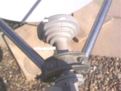
The notches are at 10 deg intervals so they give you some idea of the amount of movement required.  Unless the feed horn happens to have been assembed with the 0 marker lined up accurately with one of the polarisation planes, you can ignore the actual -40, 0, +40 markers.  In your image, the 0 deg mark appears to be at right angles to the horizontal polarisation. i.e when the 0 deg is in the middle on the top, and the LNB in the middle on the top also, the receive polarisation is horizontal.   Common sense and and plain simple observation of the orientation of the broad faces of the rectangular LNB waveguide always works.

An alternative accurate method is to place an inclinometer sideways across the body of the BUC or LNB.  It may help if you bring the elevation angle down temporarily to about 30 deg so the feed assembly is more or less horizontal.  You can then accurately determine the start position and set the polarisation angle accurately.

Best regards, Eric.
Back to top
« Last Edit: Feb 29th, 2008 at 2:38pm by Admin1 »  
 
IP Logged
 
Ex Member
Ex Member


Reply #15 - Mar 1st, 2008 at 1:09am  
actually the image above is not from the current polarization.

yes AM1 requires vertical. i have it at nominal now

i would go up and tweak to 6.6 more degrees however where the feedhorn is now there are no marks to follow so i have no idea if i am going the right way or not.
Back to top
 
 
IP Logged
 
Eric Johnston
Senior Member
★★★
Offline


Posts: 2109
Reply #16 - Mar 1st, 2008 at 8:45am  
Your scale is marked -40, 0, +40.  There are also fine marks at -90 and +90 deg where the metal casting mold has left fine lines.  One of those fine lines should be at the top right now.

For nominal vertical receive polarisation your starting position is with the LNB straight out sideways, at either side, it does not matter which.

You need to turn the feed by an amount of +6.6 deg from the starting position.  + means clockwise while you are facing towards the satellite.

You can estimate the amount of movement required as being 2/3rd of the distance between an adjacent pair of tick marks (they are spaced 10 deg apart).   If you want to be more accurate wrap a strip of paper all round the rim of the horn aperture and mark off the length of the circumference.  Then measure the length of the circumference L mm.   Calculate L * 6.6 / 360 mm.   Mark this length on the paper and reattach the paper to the horn.  Set 6.6 deg clockwise, while you are facing in the direction of the satellite.    e.g. L=250mm   250*6.6/360 = 4.6mm  so turn the rim of the aperture 4.6mm sideways from the nominal start position.

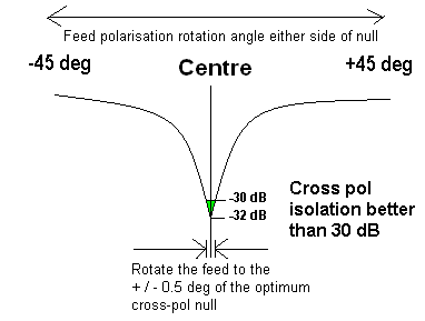
Alternatively talk to the hub while they make your modem transmit a CW carrier.  You need to get underneath or to the side of the feed so you don't obstruct the beam.  The turn the feed under instruction from the hub. Make very small movements and be very patient with the hub while they make cross pol measurements on their spectrum analyser.  They can talk you into the deep and narrow cross-pol null.

Alternatively use an inclinometer sideways across the BUC or LNB waveguide.

It really is not that difficult.

...

Best regards, Eric.
Back to top
 
 
IP Logged
 
Pages: 1