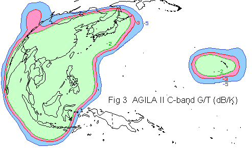
Satellite uplink - receive G/T into the satellite
Satellite uplink receive G/T is a measure of the quality of the receiver input. The G relates to the gain of the receive antenna, so a larger, higher gain antenna will have smaller beam coverage on the earth and a higher gain, expressed as dBi. The T component is the system noise temperature and this, more or less, is the addition of the low noise amplifier quality and the temperature of the warm earth background that the beam is looking at. If the noise temperature is 350K then you need to do -10log(T) to subtract it from the gain in dBi.

If you examine the satellite uplink coverage map you can determine the satellite uplink G/T for the contour line covering the uplink earth station site.
For example, at beam centre the uplink G/T might be +6 dB/K. Let us assume our uplink site is on the -4 dB contour; the uplink G/T for us is then +2 dB/K. Simply put the satellite uplink G/T, at the uplink site, (i.e. 2) into your link budget.
Typical beam edge satellite uplink G/T:
C band: Global -12 dB/K, Hemi -9 dB/K, Zone -5 dB/K, Spot -4 dB/K. The Zone -5 dB/K matched the beam coverage contours above.
Ku band: Spot 0 to +4 dB/K.
The number of dB down for the beam edge is a matter of opinion, it depends where you want to define the edge. Typically at about the -4.5 dB contour the beam is starting to drop off rapidly so there will be large variations in uplink G/T, the uplink sensitivity and downlink eirp as the satellite moves about slightly. The satellite attitude control points the antennas at the earth and it is difficult to maintain the pointing to an accuracy better than +/- 0.1 degrees.
If you have come from the general purpose link budget page, you can go back to it and not lose any figures you have inserted by clicking on the BACK button now.
If you are designing a satellite you may estimate the uplink G/T by considering the uplink antenna gain and the satellite receive system noise temperature. The uplink antenna gain is easy to calculate. The uplink system noise temperature is obviously related to the quality of the receive low noise input amplifier on the satellite, waveguides and antenna itself, but in the case of satellites where the up-link beam is pointed at the earth and the earth's surface occupies the full area of the beam then the thermal noise from the earth surface (clouds, land, ice and water) becomes a major factor. If the surface is all land foliage then the noise temperature contribution may be 300K. The sea has a lower value as it is reflective and the satellite is seeing a reflection of the cold deep space to some extent. A spacecraft whose beam is pointed substantially at cold space (such as an inter-satellite link or aimed at a distant planet etc) would have a negligible noise contribution from the background.
G/T = antenna gain - 10 log (system noise temperature ) dB/K
Example: G/T = 30 - 10 log(350) = 30 - 25.4 = +4.6 dB/K (beam centre)
Return to the general purpose satellite link budget calculator with the figures deleted.
|
Copyright Satellite Signals Limited © 2015 all rights reserved. |