|
|
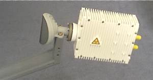
Ku band TRIAs
TRIA means combined Transmit-Receive Integrated/Isolation Assembly.
Comprising 3 watt Ku band transmit BUC and universal LNB (PLL LO switchable 9.75, 10, 10.6 or 11.3 GHz)
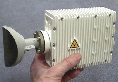
Compact transmit-receive integrated assembly comprising 3 watt Ku band transmitter block up converter (BUC) and a low phase noise PLL LNB with switched local oscillator frequencies and integrated ortho-mode transducer (OMT) and filters which separate the horizontal and vertical polarisations and the transmit and receive frequencies. It combines all those ugly old OMT, waveguides and transmit reject filter into one neat compact assembly. A key advantage is that you don't need to pre-choose the type of LNB. In this case a multi-frequency LO universal LNB is offered with multiple local oscillator frequencies, switchable using an external dongle that fits to the LNB cable next to the modem and which allows the LNB LO frequency and co-pol or cross-pol operation to be selected using DIL switches.
Transmit 14 to 14.5 GHz. Receive 10.7 to 12.75 GHz. Co-pol or x-pol operation
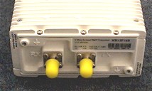
Dual F connectors for compatibility with indoor satellite modems
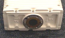
Note the clearly marked transmit and receive polarisations (big arrows for TX and RX)
The low phase noise PLL type LNB uses phase lock loop technology, making this ideal for narrow band SCPC as well as advanced modulation techniques 8-PSK, 8-QAM and 16-QAM which make more efficient use for the satellite bandwidth and so potentially reduce monthly costs by 2/3 or 1/2 of present costs. It is ideal for DVB-S2 when operating at the highest order modulation methods.
Transmit frequency: The satellite uplink frequency is in the range 14 - 14.5 GHz. The BUC up converter frequency is 13.05 GHz so your modem transmit frequency needs to be in the range is in the 950 to 1450 MHz
Receive frequency: The PLL LNB has multiple alternative local oscillator conversion frequencies which may be selected using an external dongle located in the LNB cable next to the indoor modem. DIL switches allow selection of the appropriate LNB local oscillator frequency to suit your VSAT modem receive range. Cross-pol operation and co-pol operation may be selected also.
| Modem L band cable receive range |
| Vipersat CDM-570L 950 - 1950 MHz |
| iDirect 3000, 5000, 7000 950 - 1700 MHz |
| Linkstar 950 - 1450 MHz |
| LinkStar S2 950 - 1750 |
| SMR-5000L 950 - 1750 |
| Shiron R256L 950 - 1535 |
| DVB-S2 card / receiver 950 - 2150 MHz |
Technical TRIA specification:
Model: XR13F16 Transceiver SeriesIntegrated Ku TRIA: OMT, 3W BUC and LNB
Cross polarisation (XPD) on Common Port Tx 35 - 40 dB, Rx 30
RF Input Frequency Range:
Low Band 10.70 - 11.70 GHz
High Band 11.70 - 12.75 GHz
IF Output Frequency Range
Low Band 950 - 1950 MHz
High Band 1100 - 2150 MHz
Local Oscillator Frequencies (selectable using indoor dongle),
Low Band 9.75 GHz, 10 GHz, High Band 10.60 GHz and 11.3 GHz
Local Oscillator Frequency Tolerance
XR13F16 ±50 ppm
XR13F16Z ±10 ppm
XR13F16S ±3 ppm
XR13F16X ppm Dependent on
External 10 MHz Reference
Local Oscillator Phase Noise (SSB)
@ 1 kHz -60 dBc/Hz
@ 10 kHz -80 dBc/Hz
@ 100 kHz -100 dBc/Hz
Receive Sub-system (LNB with PLL internal or External Ref):
LNB Noise Figure @ 25˚C typ 0.9 max 1.3 dB Tx On (Carrier On or Off)
Equivalent Noise Temperature typ 69 - max 104 K Tx On (Carrier On or Off)
RF Input Return Loss 3 dB On Common OMT Port
Conversion Gain min 50 typ 56 max 62 dB
In-band Variation 6 dB Max-Min
In-band Segment Variation Any 36 MHz 1.5 dB Max-Min
Image Band Rejection typ 60 max 80 dB
IF Output IP3 +10 dBm
IF Output Spurious C/No In-band 60 dBHz Tx On, Carrier On
C, Out-of-band/100 kHz -25 dBm Tx On, Carrier On
IF Output Spectrum Inversion: No
IF Output Impedance: 75 Ohm
IF Output Return Loss: 8 dB
IF Output Connector F-type Receptacle
Supply Voltage/22 kHz Tone Band Switch Control acc. EN61319
Low Band voltage Selected 9.0 - 14.0 V
High Band voltage Selected 16.0 - 25.0 V
Low Band tone Selected 0 or 100 mV 18-26 kHz; 5-15 μs slope; 40-60%
High Band tone Selected 600 mV +/-200mV, 18-26 kHz; 5-15 μs slope;
40-60%
Supply Current typical 150 max 180 mA
Tx Sub-System (BUC with External Ref.)
IF Input Frequency Range 950 - 1450 MHz
RF Output Frequency Range 14.00 - 14.50 GHz
Local Oscillator Frequency (Nominal) 13.05 GHz
Local Oscillator External Reference Input Frequency (Nominal) 10 MHz Sine
Wave, Capture Range ±15 ppm
Input Level min -10 typ 0 max 5 dBm
Return Loss -10 dB
RF Output Power Linear Service -1 dB Gain P1dB 34.5 dBm on OMT Common Port
Including Variation Over Frequency, Temp. and Lifetime 33.5 dBm
RF Output Return Loss 8 dB Linear Operation
IF Input Drive Power Nominal Operation -19 dBm
No Damage Level +5 dBm
IF input Impedance (Nominal) 75 Ohm
IF Input Return Loss 10 dB
IF Input Connector F-type Receptacle
Conversion Gain, Linear Operation 50 53 56 dB
In-Band-Segment Variation (any 2 MHz Segment) 0.5 dB Maximum-Minimum
Supply Voltage 15 - 30 V
Supply Current typ 1.0 max 1.3 A 24 V, After Inrush, Carrier On
Environmental:
Mass 1600 g Radio Module without Feed
Operating Temperature -40 55 ˚C
Moisture/Humidity Protection IP67
Mechanical Specifications
Tx Connector F-Type (N-Type is also available)
Grounding Tag (2 places)
Rx Connector F-Type
Waveguide 2518.5 mm 3/8 in x 32 UNEF 2A R17.5 mm
Adaptor rings available.
Dimensions: 174 mm, 63 mm, 35 mm
All designs, specifications and availabilities of products are subject to change without notice. As of April 2016 I am not sure new ones are still available. There are some available on the second hand market.
News 4 Oct 2007
A 5 watt version is now available. It has slightly larger dimensions.
The TRIA comes with a set of adaptors for Andrew, Prodelin, Patriot feed horns etc.
The TRIA comes with an external dongle (to be connected in the LNB cable near the indoor modem) to allow the multiple alternative LNB LO frequencies to be selected.
Contact details: Roger Boddy. Phone: +44(0)7956 109 337
By Post: Global Teleports (UK) Ltd, Suite 105 107, The Bio Park, Broadwater Road
Welwyn Garden City, Hertfordshire, AL7 3AX, England.
Andrew Transceiver XR1316 XR1326 pdf 1.2 Mbytes (DRO +/-3 MHz)
Andrew Transceiver XR13F16pdf (PLL LNB, various stabilities)
|
Page new 8 June 2007, amended 16 April 2016, 26 July 2026. |