|
|
LNB: Low noise block downconverter
Have you ever wondered what is an LNB and what is an LNB LO frequency ? Here is some information about LNBs that I hope will help explain matters.
The abbreviation LNB stands for Low Noise Block. It is the device on the front of a satellite dish that receives the very low level microwave signal from the satellite, amplifies it, changes the signals to a lower frequency band and sends them down the coax cable to the indoor receiver.
The expression low noise refers the the quality of the first stage input amplifier transistor. The quality is measured in units called Noise Temperature, Noise Figure or Noise Factor. Both Noise Figure and Noise Factor may be converted into Noise Temperature. The lower the Noise Temperature the better. So an LNB with Noise Temperature = 100K is twice as good as one with 200K. C band LNBs tend have the lowest noise temperature performance while Ka LNBs have the highest (worst).
The expression Block refers to the conversion of a block of microwave frequencies as received from the satellite being down-converted to a lower (block) range of frequencies in the cable to the receiver. Satellite down-link broadcasts are mainly in the range 4 to 12 to 21 GHz.
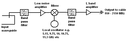
Low noise block downconverter (LNB) diagram
This diagram shows the input waveguide on the left which is connected to the collecting feed or horn. As shown there is a vertical pin through the broad side of the waveguide that extracts the vertical polarisation signals as an electrical current. The satellite signals first go through a band pass filter which only allows the intended band of microwave frequencies to pass through. The signals are then amplified by a Low Noise Amplifier and thence to the Mixer.
At the mixer-stage, the signals let through by the input bandpass-filter are mixed with the signal generated by the local-oscillator and this process creates a multitude of sum and difference signals. **
Amongst the mixer output products are the difference frequencies between the wanted input signal and the local oscillator frequency. These are the ones of interest. The second band pass filter selects these and feeds them to the output L band amplifier and into the cable. Typically the output frequency = input frequency - local oscillator frequency. In some cases it is the other way round so that the output frequency = local oscillator frequency - input frequency. In this case the output spectrum is inverted.
Examples of input receive frequency band, LNB local oscillator frequency and output frequency band are shown below.
C band is 3.4 - 4.8 GHz. Ku band is 10.7 - 12.75 GHz. Ka band is 19.2 - 21.2 GHz.
| Input freq. band C, Ku, Ka GHz from sat. waveguide | Loc Osc. (LO) freq. | Output L band into cable (MHz) | Notes |
| 3.4-4.2 | 5.15 | 950-1750 | inverted output spectrum |
| 3.625-4.2 | 5.15 | 950-1525 | " |
| 4.5-4.8 | 5.75 | 950-1250 | " |
| 4.5-4.8 | 5.76 | 960-1260 | NJS 8488 |
| 4.5-4.8 | 5.95 | 1150-1450 | " |
| 10.7-11.7 | 9.75 | 950-1950 | |
| 10.95-11.7 | 10 | 950-1700 | |
| 10.95 - 12.15 | 10 | 950-2150 | Invacom SPV -50 SM |
| 11.45-11.95 | 10.5 | 950-1450 | |
| 11.2-11.7 | 10.25 | 950-1450 | |
| 11.7-12.75 | 10.75 | 950-2000 | Invacom SPV -60 SM |
| 12.2 -12.7 | 11.25 | 950-1450 | DISH |
| 12.25-12.75 | 11.3 | 950-1450 | Invacom SPV -70 SM |
| 11.7-12.75 | 10.6 | 1100-2150 | |
| 11.7-12.2 | 13.85 | 2150-1650 | DISH FSS inverted |
| 12.2 - 12.7 | 14.35 | 2150-1650 | DISH PRO inverted |
| 19.2-19.7 | 18.25 | 950-1450 | |
| 19.7-20.2 | 18.75 | 950-1450 | |
| 20.2-20.7 | 19.25 | 950-1450 | |
| 20.7-21.2 | 19.75 | 950-1450 | |
| 19.7-20.2 | 21.2 | 1000-1500 | Invert Saorsat |
| 18.2-19.2 | 17.25 | 950-1950 | Norsat 9000 |
| 19.2-20.2 | 18.28 | 950-1950 | Norsat 9000 |
| 20.2-21.2 | 19.25 | 950-1950 | Norsat 9000 |
All the above illustrate a simple LNB, with one LNA and one LO frequency.
More complex LNBs exist, particularly for satellite TV reception where people wish to receive signals from multiple bands, alternative polarisations and probably simultaneously.
Dual-band LNBs
Ku band LNBs typically have two alternative local oscillator frequencies, for example 9.75 GHz and 10.6 GHz with the higher frequency option selected using a 22 kHz tone injected into the cable. Such an LNB may be used to receive 10.7 - 11.7 GHz using the lower 9.75 GHz LO frequency or the higher band 11.7 - 12.75 GHz using the higher 10.6 GHz LO frequency.
Some Ka band LNBs may have as many as 4 different local oscillator frequencies.
Dual polarisation LNBs
The LNB shown in the diagram above has one wire probe going into the waveguide to pick up vertical polarisation. If the input waveguide is circular or square cross-section it can support two polarisations and it can be arranged for there to be two input probes at right angles, thus allowing two alternative polarisations to be extracted (vertical or horizontal, or left hand or right hand circular polarisation, LHCP or RHCP), either one or the other. Dual polarisation LNBs may commonly be switched remotely using two alternative DC supply voltages. e.g. 13 volts makes it receive vertical polarisation and 19 volts make it receive horizontal polarisation.
"Universal" Ku band LNB
At Ku band, a domestic user with just one set-top box will have an LNB with single output cable. Using cable DC supply voltage (13 or 19 volts) and 22 kHz tone (ON/OFF) the indoor set top box selects the polarisation and low or high band.
Multi-LNBs
It is possible to have two input probes (at right angles), each with their own active LNA amplifier, one for each polarisation.
The outputs from each LNA might then be split to go to two mixers, each with a different local oscillator frequency. This way you finish up with four wires, fixed, one for horizontal+high band, one for horizontal+low band, one for vertical+high band and one for vertical+low band. This arrangement is called a "Quattro LNB". Such an arrangement is useful at a head end antenna, feeding a cable TV network, but is not suitable for home use since each cable would carry just one fixed polarisation and part band.
A "Quad" LNB has 4 output cables, with each cable having independent control of its selected polarisation and band. This is the same as having four universal LNBs. Each cable has independent control of its selection. A "Quad" LNB is suitable for a customer site with up to 4 set-top box receivers, where each set-top box receiver is able to select their particular wanted polarisation and high or low band. In a domestic situation viewers in 4 different rooms, each with individual set top boxes and screens can each watch TV channels on any band or polarisation.
Stacked frequency LNBs
The DISH-PRO system (as an example) uses stacked blocks of frequencies in the LNB output, one block from each polarisation. This means no switching of polarisation and that all signals are available simultaneously all of the time at the set top box end. The DC is supply normally fixed at 19 to 20 volts. High quality RG6 coax cable essential for working up to 2150 MHz
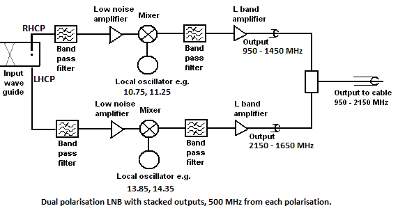
Dual polarisation LNB with stacked outputs
In the case of a circular polarisation system the input waveguide contains a polariser which converts dual circular polarisation to two linear polarisations, extracted by two probes at right angles to two low noise amplifiers. See the image above.
The X symbol above, within the input waveguide, is represents a device called a 'polariser' (in this case acting as depolariser !) and may comprise a flat piece of dielectric (plastic) mounted at 45 degrees to the probe pins.
Example frequency conversions are shown below
Input 12200-12700 R - 11250 LO = 950 -1450 IF output
Input 12200-12700 L - 14350 LO = 2150 - 1650 IF output
or, for a linear polarised satellite system with a limited 500 MHz bandwidth. (AMC-21 linear FSS ?)
Input 11700-12200 H - 10750 LO = 950 -1450 IF output
Input 11700-12200 V - 13850 LO = 2150 - 1650 IF output
The gap in the output spectrum makes it easier to combine filter and avoid interference and noise
LNB Frequency stability
All LNBs used for satellite TV reception use dielectric resonator stabilised local oscillators. The DRO is just a pellet of material
which resonates at the required frequency. Compared with a quartz crystal, a DRO is relatively unstable with temperature and frequency
accuracies may be +/- 250 kHz to as much as +/- 2 MHz at Ku band. This variation includes both the initial value plus variations of temperature
over the full extremes of the operating range. Fortunately most satellite TV carriers are quite wide bandwidth (like 27 MHz) so even with 2 MHz error the indoor
receiver will successfully tune the carrier and capture it within the automatic frequency control capture range.
If you want the LNB for the reception of narrow carriers, say 50 kHz wide, you have a problem since the indoor receiver may not find the carrier at all
or may even find the wrong one. In which case you need a rather clever receiver that will sweep slowly over a range like +/- 2 MHz searching
for the carrier and trying to recognise it before locking on to it. Alternatively it is possible to buy Phase Lock Loop LNBs which have far
better frequency accuracy. Such PLL LNBs have in internal crystal oscillator or rely on an external 10 MHz reference signal sent up the cable
by the indoor receiver. PLL LNBs are more expensive. The benefit of using an external reference PLL LNB is that the indoor reference oscillator
is easier to maintain at a stable constant temperature. Ka band LNBs operate at such high frequency that they can need phase look loop frequency control
unless the wanted carriers are very large bandwidth. An internal PLL uses a crystal oscillator in the LNB. An external reference PLL uses a
10 MHz reference supply from the customer's indoor modem or receiver.
LNB Phase noise
All modern DRO LNBs are sold as 'digi-ready'. What this means is that some attention has been paid in the design to keeping the phase noise down so as to facilitate the reception of digital TV carriers. The phase noise of DRO LNBs is still far worse than for PLL LNBs. What good phase noise performance is really needed for is for the reception of low bit rate digital carriers and for digital carriers using high spectral efficiency modulation methods like 8-PSK, 8-QAM or 16-QAM modulation, which reduce the bandwidth required but need more power from the satellite, a bigger receive dish and better quality PLL type oscillators in both the transmit and receive chains.
Phase noise is unwanted small random variations in the frequency and it interferes with the wanted frequency shift keying modulation which carries the customer information.
LNB supply voltages
The DC voltage power supply is fed up the cable to the LNB. Often by altering this voltage it is possible to change the polarisation or, less
commonly, the frequency band. Voltages are normally 13 volts or 19 volts.
Perfect weatherproofing of the outdoor connector is essential, otherwise corrosion is rapid. Note that both the inner and outer conductors must
make really good electrical contact. High resistance can cause the LNB to switch permanently into the low voltage state. Very
peculiar effects can occur if there poor connections amongst multiple cables to say an LNB and to a transmit BUC module as the go and return DC supplies
may become mixed up and the wrong voltage applied across the various items. The electrical connections at the antennas between the LNB and the BUC
chassis are often indeterminate and depend of screws in waveguide flanges etc. Earth loop currents may also be a problem - it is possible
to find 50 Hz or 60 Hz mains currents on the outer conductors - so be careful. Such stray currents and induced RF fields from nearby
transmitters and cell phones may interfere with the wanted signals inside the cables. The quality and smoothing of the DC supplies used for
the LNBs is important.
LNB Transmit reject filter
Some LNBs, such as those from Invacom, incorporate a receive band pass, transmit band reject filter at the front end. This provides both good image reject response for the receive function but also protects the LNB from spurious energy from the transmitter, which may destroy the LNB.
How to test an LNB:
Check with a current meter that it is drawing DC current from the power supply. The approx number of milliamps will be given by the manufacturer. Badly made or corroded F type connections are the most probable cause of faults. Remember that the centre pin of the F connector plug should stick out about 2mm, proud of the surrounding threaded ring.
Use a satellite finder power meter. If you point the LNB up at clear sky (outer space) then the noise temperature contribution from the surroundings will be negligible, so the meter reading will correspond to the noise temperature of the LNB, say 100K (K means Kelvin*. 0K is absolute zero temperature, or -273 deg Centigrade, Kelvin units are the same magnitude as degrees Centigrade, so a room temperature of +17 deg C is the same as 273+17=290K). Boiling water at +100 deg C is the same as +373 K.
If you point the LNB away from straight up and down towards your hand or the ground, which is at a temperature of approx 290K then the noise power reading on the meter should go up, corresponding to approx 390K (100K +290K). If you have the LNB mounted in an antenna you should get the same effect, a big increase in noise output when the beam from the dish is pointed at the ground or trees etc. Pointing at the sun should give a much bigger increase, but be careful not to overheat the LNB horn if the dish surface is optically reflective (i.e. not a matt paint finish) and similar to a mirror and reflects light and heat.
Note that LNBs may fail on one polarisation or on one frequency band and that the failure mode may only occur at certain temperatures.
If you choose to try a replacement LNB in a VSAT system check the transmit reject filter and supply voltage - you don't want to be one of those people who keeps blowing up LNBs trying to find a good one !
Overloading an LNB
If you have a very large dish, say 7m diameter and point it at a satellite whose signals are intended for reception by small 70cm diameter antennas then the 20 dB increase in total power of the signals into the LNB may be sufficient to overload some of the transistor amplifier stages inside. This is not always obvious. Measuring the composite output power of the LNB using a power meter is suggested and comparing this with the -1 dB compression point in the manufacturer's specification. An alternative is to do an antenna pattern test on both a high power and a low power satellite. Any non linearity problem with the high power satellite is then clearly visible. Special low gain or high power output level LNBs are available for use with large dishes.
* [edit 1 Feb 2016] I've updated the definition of "Kelvin". It has been pointed out that you should not use the expression "degrees Kelvin" but rather use the word "Kelvin" or the abbreviation "K" alone.
** [edit 1 Nov 2018] I've replaced the original text about the input signal and local oscillator signal being "scrambled up" in the mixer with better wording suggested to me in an email.
Interference into C band LNBs
The band 3.625 - 4.2 GHz is under increasing pressure from other spectrum users such as WiFi, WiMAX and, in the future, beyond 2020, from 5G. These new services may operate just below or within the satellite band. If a WiMAX transmitter is nearby then it may interfere into your LNB. The solution is to use a band pass filter in front of your LNB which will restrict the range of of frequencies you can receive. An older 3.7-4.2 may be better than a modern wide band 3.625 - 4.2 GHz type. In future, if 5G grabs most of the satellite band, then 4 - 4.2 GHz filters/LNB will be needed for satellite use. Some C band sites need site shielding with earth banks, foliage or walls to reduce interference from nearby terrestrial sources.
Useful links to suppliers who do professional LNBs for sale suitable for VSAT applications:
A variety of C-band, Ku band and Ka band LNBs from Norsat
I have just picked these suppliers as ones I know of well. You are welcome to suggest others to me eric@satsig.net that you may have found, that give good service.
|
If your think there are errors in the above advice please suggest new text paragraphs and send to me by email. eric@satsig.net You are also welcome to send me pictures of your LNB/antenna. Many thanks. ► Page created 21 March 2006, last edited 13 July 2026. All pages on this satsig.net web site are Copyright Satellite Signals Limited (c) 2006 all rights reserved. |