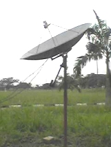
Setting up a satellite dish polar mount just north of the equator
Start: Find you latitude. e.g. 6.5 deg north. Input this to the calculator together (optionally) with the longitude, say 3.5. If you input your longitude put the same figure also as the satellite orbit location as this will give additional azimuth-elevation angles for a hypothetical satellite due south of you.
Example assuming: The results from the polar mount satellite dish pointing calculator say:
The MAIN MOTOR AXIS BEARING angle must be 6.7 degrees.
The SMALL DOWNWARD TILT ANGLE of the dish must be 1 degree.
Viewed from the east, facing west. The actuator is centralised and the dish is aimed at the highest satellite, due south of you on the same longitude, elevation angle 82.33 deg and azimuth due south ( 180 deg true bearing ).
Moving the actuator either way will tip the dish sideways and downwards towards the east or towards the west.
Main axis angle = 6.68 deg. Slight downwards tilt of the dish = 1 deg.
The polar mount head unit, attached to the pole, is an L shaped part. Near the equator the top of this is almost level and the polar mount main axis is also almost horizontal. In the example here, the polar mount main axis angle is 6.7 degrees. The pink part should be tilted by 6.7 degrees. ( The actual tilt in the diagram is exaggerated slightly, it shows a tilt of 10 degrees. )
The dish is attached at B, shown by the blue line.
The dish needs to be tilted down 1 deg by making distance A fractionally shorter than distance C.
tan = opposite / adjacent, so tan 1 deg = (C-A)/B so
tan 1 deg = 0.0174 so 0.0174 x B = C - A so A = C - 0.0174 x B
Measure B and C, calculate A, and then set A exactly.
The entire head unit must be rotated on the pole and clamped so that it is aimed due south, to the left in the diagram.
In the older image on the right, the top piece is horizontal right now, which is wrong. Is there any way it can be tilted up on the right hand side?
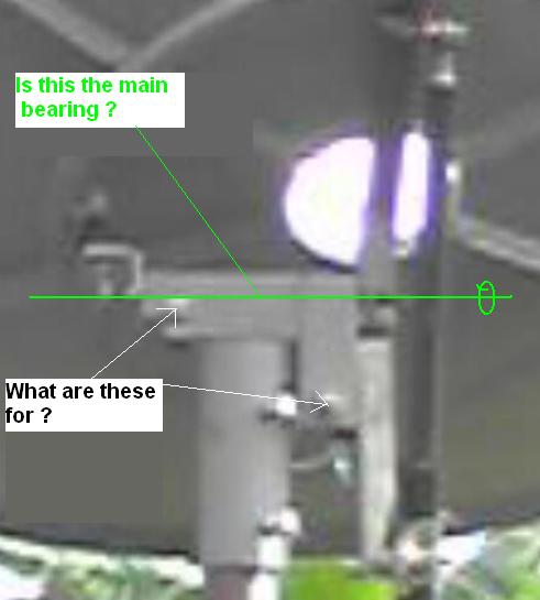
Does the pink screw adjuster, as suggested in the diagram, exist ?
What are the two apparent "end of bolts", as marked, for ?
Is the main axis bearing line along the green line or does the mount rotate above an axis line higher up ?
More news when we hopefully get it to work !!
Finally..
Eric Thanks. I tried out what you said and presently get about 100 FTA stations (whoa) while about 30 are scrambled.
Thanks once again. I hope others use my situation as a case study in setting up theirs.
Back to setting up a polar mount satellite dish with motor drive
Read below for the satsig forum story behind this page:
|
|
| Eric Johnston Member |
It is to be expected that signals from some satellites will be took weak to be displayed - even if your mount is set up OK. |
| tosin Member |
I have sent pictures of my set up to your e-mail address. I tried to take them in a way that you will understand the 3 dimensional placement of the dish. |
| Eric Johnston Member |
Have a look at the top of this page |
| tosin Member |
Believe me, your construction was great. Now I got that 1deg tilt perfectly but the 6.7 deg tilt is the problem. The head unit attached to the polar mount is T-shaped and fits
into the pole straightaway without any opportunity of adjusting it. I sent a picture of it now to your e-mail. |
| Eric Johnston Member |
I've added a picture of the L shaped metal at the top of the pole. |
| tosin Member |
Your diagram from the actual pictures I sent to you have solved all the problems I had. I thought that joint was a T- joint that should not be adjusted and rather the head
unit as a whole. I now know where to tilt to 6.7 deg on the main bearing. God, I am very grateful. I will put all I have to do as you have shown me. I owe it to you and how much you have been helping
us. The result will be out as soon as possible (latest on Saturday). |
| tosin Member |
Eric Thanks. I tried out what you said and presently get about 100 FTA stations (whoa) while about 30 are scrambled. |
|
Started 23 Sept 2005, amended 24 Feb 2014 |