|
|
Clipper 2015-2016 race 1, from Southend to Rio Clipper 15-16 race 14 final RESULTS Sailing at Perdepera, Sardinia Mark Warner Sailing at San Lucianu Maxi sailing (Fuerteventura) |
Clipper Ocean Racing (weekend) |
How a sail works
The purpose of the sails to make air flow smoothly in a curved fashion. Doing this then causes a force on the sails according to the pressure difference that appears between the two sides.
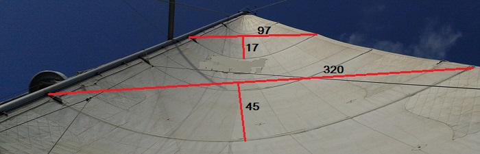
Example measurements for camber percentage:
Chord = 97, Depth = 17 Ratio= 17%
Chord = 320, Depth = 45 Ratio= 14%
Units of measurement are arbitrary, for example mm on your mobile images
display. Hold your camera device close to the middle of the foot (bottom edge) of
the sail.
We hope that the air, on either side of the sail, remains "attached" in a smooth stream. If the sail is too curved the air flow tends to break down into eddies, which is bad.
Causing the air on the front and rear to go in smooth curves creates a centrifugal force on the sail, as the air flow must be pulled towards the centre of curvature like a weight on the end of a string - otherwise the air would flow straight on. You can't make anything move in a curve unless you apply a sideways force to it.
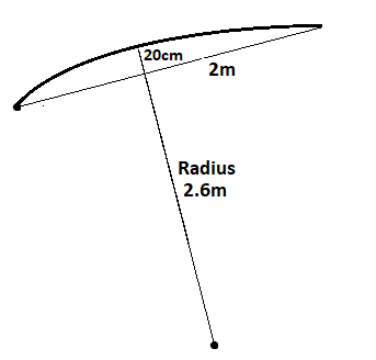
For example, if the sail is 5m high and 2m wide at the foot and curved 20cm (10%) deep and affects a total of approx 5 cubic metres of air at a speed of 10 knots (Force 3-4 Beaufort scale), then the force needed to make this 5 cubic metres air move in a curve may be calculated as follows:
Mass of air moving in curve = 5 cubic m x 1.225 kg/cubic.m = 6.125 kg (approx)
Speed of air, V = 10 knots = 10 x 0.5144 m/s = 5.144 m/s
The radius of the curved airflow may be calculated using this formula:
W = width of sail (2m) C = camber depth (0.2m)
Radius of curved airflow R = C / 2 + (W x W) / (8 x C) = 0.2 / 2 + (2 x 2) / (8 x .2) = 2.6 m
Centrifugal force = M x V x V / R N (N means units of Newton)
It is all well and good to know the force in Newtons but who knows what this means?. Well to get an idea, you need to apply a pull up force of about 9.8 Newtons to lift a mass of 1 kilogram (or 2.2 pounds) if you are on the earth's surface.
The results below include the output forces expressed as "kg force" which is a non standard metric unit defined as the gravitational force exerted on a 1-kilogram mass under standard Earth gravity!
This calculator below works out what centrifugal force applies to the sail and how this may be resolved into in-line driving force and sideways capsizing force.
Default values assume 10% camber and close hauled with sail 10 deg off the centreline.
The thickness of the air affected is assumed to be half the width of the sail along the foot, at the boom. All rather approximate.
If you play with this a bit you will learn that the total force on the sail may be increased by increasing the camber from 10% to 12%, or the total force decreased by reducing the camber from 10% to 5%.
Also, and rather important, the more the sail is let out the greater the component of total sail force is in line with the boat. Don't keep the boom in too tight otherwise part of the sail (typically the rear part of the mainsail) will be simply pulling you over or even backwards!
How to trim the Sail
If your helm is trying to steer a straight course and not aiming for an upwind or downwind objective, then you need to actively trim the sails for maximum forwards force. For trimming the sail, let it out as far as you can without allowing the smooth curved airflows to break down. Watch out for no rippling of the sail just back from the leading edge (luff wire on the jib or the mast on a mainsail) and smooth trailing of the tell-tails all down the leech (back edge) of the sail(s). If you have see-through windows in the sails near the luff (front edge) try to keep the tell-tails either side flowing smoothly.
The camber may be adjusted up to about 12 %, when the smooth airflows may start to break down. You may safely decrease the camber to reduce both driving and capsizing forces if you can't reef the sail or use smaller sail.
If your helm is aiming for an upwind or downwind objective then adjust and initially set the sails either for close-hauled or downwind sailing and the leave the helm to actively steer to keep the air flows smooth. If 12% causes excessive healing then flatten the sail or apply a reef. Note that regular tacking and gybing is appropriate for upwind and downwind zig-zag sailing to maximise Velocity Made Good (VMG), both upwind and downwind..
In the calculation above, note that the angle of the sail to the centre line of the boat varies as you go higher up the mast, due to twist in the sail. Use an angle about 1/3 of the way up.
Next steps:
Measure the force on the sail using a differential air pressure gauge incorporated in middle of the sail cloth. Make it an electronic gadget able to bluetooth/WiFi the output data.
Measure the boom angle using some kind of angle resolver able to bluetooth/WiFi the output data
Combine the outputs on mobile phone and display moving graph of the forward drive force as Force on Sail x Sin(Boom Angle).
This development should help with sail adjustment (while sailing a course) or with the steering (while upwind or downwind sailing). Whether my theory is right or not does not matter at all.
Feedback
Feedback welcome, click to email me eric@satsig.net to say what you would like to add below...
Do the results even approximate to reality ?
Update to this page. April/May 2026:
Here below are some new measurements for both the jib foresail chord and the mainsail chord. In both cases I have made two measurements using the dark lines on the sail material. The measurements may be made on the images (in say mm) and the ratio calculated. In all case the resulting chord ratio is shown as a percentage.
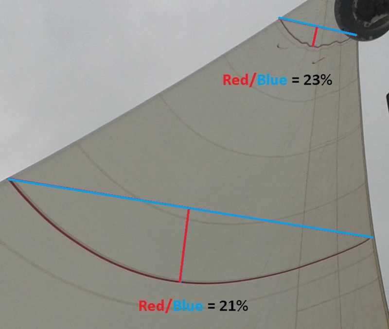
Example Jib or Genoa foresail chord ratio. The chord ratios of 21% to 23%
sound much too high to me. A tighter forestay would make a small improvement
but my guess is that moving the jib sheet anchor point further aft (backwards)
would be more helpful. In this case the jib car (slider) was already at its furthest aft position in its track.
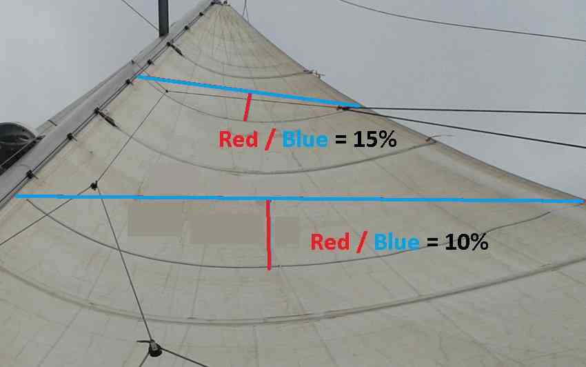
Example Mainsail chord ratio. The chord ratios of 10% to 15% sound good to me.
As above, feedback is welcome, send me your pictures, click to email me eric@satsig.net
|
Page created 15 June 2018, amended 28 May 2026 ECJ (c) 2018 Copyright. All rights reserved. |