|
|
Middle East satellite internet coverage |
How to find offset angle of dish |
AGILA 2, FULL C-BAND TRANSPONDER PERFORMANCE PARAMETERS
1. Introduction
This web page provides the key performance parameters of the C-band transponders of Mabuhay Philippines Satellite Corporation (MPSC) Agila - II satellite to assist customers in the design of their earth stations.
Some time has passed since this page was written in 2002, but I am keeping it here as the full set of satellite transponder parameters is a good basis for practising link budget calculations.
Note that since orbital positions are allocated by international agreement, it may be necessary, because of future reallocation, for MPSC to interchange or relocate the satellite. Also, due to potential RF channel or satellite failures, customers may be required on short notice to change RF channels, frequencies within a channel and/or satellites. Customers should therefore ensure that their transmitters and receivers have the necessary frequency agility.
2. Satellite Orbital Location and Stationkeeping Accuracy
Orbital Location
146° E Longitude
North - South Station Keeping ± 0.05°
East - West Station Keeping ± 0.05°
Attitude (beam pointing)
± 0.15°
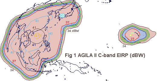
3. Downlink Effective Isotropic Radiated Power (EIRP)
Fig 1 provides the downlink EIRP contour of the Agila - II typical C-band
channel.

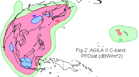
4. Uplink Saturated Flux Density (SFD)
Fig 2 provides the SFD contour of the Agila - II typical C-band channel.

The Agila - II C-band channels contain commandable attenuators that control channel gain and hence, saturation flux density. The attenuator can be set from 0 to 31.5 dB in 0.5 dB steps. The nominal setting is 20 dB attenuation equivalent to gain step 23 and SFD of -88 dBW/m2 at G/T of -3 dB/K.
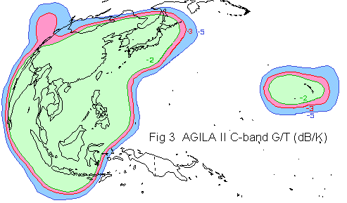
5. Uplink G/T Ratio dB/K
Figure 3 provides the uplink G/T contour of the Agila - II typical C-band
channel.

6. Transponder Frequency Plan
The satellite has frequency and polarization plans. (not yet included here).
7. Cross-polarization Isolation
The spacecraft transmit antenna has cross polarization of more than 27 dB over 100% of the coverage area.
8. TWTA Amplitude Transfer Characteristic
A typical TWTA amplitude transfer characteristic is shown in the curve (not yet available here).
9. Frequency Response Of Transponder Channel
The frequency response meets the requirements shown below at any frequency
between the offsets shown.
+/- 12 MHz Input -0.7 dB Total -1.1 dB
+/- 18 MHz Input -1.1 dB Total -2.0 dB
10. Group Delay Response of transponder Channel
Transponder group delay limits are shown below:
0 MHz Input 0
Overall 0
± 8 MHz Input 3.74
Overall 10.95
± 12 MHz Input 6
Overall 21.64
± 16 MHz Input 12.35 Overall 49.93
± 18 MHz Input 26.41 Overall 109.5
11. Gain Slope
The gain slope falls within the masks defined below (dB/MHz)
± 12 MHz Input 0.06 Total 0.13
± 14 MHz Input 0.07 Total 0.2
± 16 MHz Input 0.2
Total 0.5
± 18 MHz Input 0.7
Total 1.6
12. Total Phase Shift
The total phase shift does not exceed the values given below. Total phase
shift is defined as the maximum shift of carrier phase when a single unmodulated
carrier is varied from saturation and below.
Input Level (dB Below Saturation) and Maximum Relative Phase Shift (°)
Input Level 0 dB Phase Shift
(°) 49
Input Level -3 dB Phase Shift (°)
38
Input Level -6 dB Phase Shift (°)
27
Input Level -9 dB Phase Shift (°)
16
Input Level -12 dB Phase Shift (°) 10
Input Level -14 dB Phase Shift (°)
7
Input Level -20 dB Phase Shift (°)
0
13. System Redundancy
The Agila - II satellite has the following redundancy scheme:
Receiver Redundancy
4-for-2; tolerates two failures without loss of receive capability
Channel Amplifier/TWTA redundancy
Two rings with 19-for-15 redundancy
14. Beacon Technical Data
Beacon frequencies are:
Horizontal Polarization : 4196.000 MHz
Vertical Polarization : 4198.000 MHz
15. For further information:
MAKATI OFFICE MABUHAY SPACE CENTER
20/F PLDT Tower-2, Ayala Avenue, Group 5, Naval Magazine
Makati City, 1226 Philippines Subic Bay Freeport Zone, 2222, Philippines
Tel. (63-2) 887-5788; Fax (63-2) 887-5789 Tel (63-47)252-9004; Fax
(63-47)252-9002
|
This page was amended 19 Nov 2002, last amended 6 August 2015 with style changes and more links added, amended 15 Apl 2020 after character corruption. |